
Optical Theremin

The project involves constructing a Theremin-like instrument that uses two photodiodes as sensors to control sound parameters, specifically pitch and amplitude. The operational amplifier functions as a current-to-voltage converter, amplifying the minute currents produced by the photodiodes when exposed to varying light levels. The first circuit focuses on amplitude control, while the second circuit is dedicated to frequency modulation. The connections between the MyDAQ, operational amplifiers, and photodiodes are critical for achieving the desired sound output.
The use of NI LabVIEW software allows for further exploration and manipulation of the signals generated by the photodiodes, providing a platform for users to design unique soundscapes. The flexibility of the system encourages experimentation with different light sources and distances to create a wide range of auditory experiences. The Theremin's design and functionality can be adapted based on user preferences, making it an engaging project for those interested in electronics and sound engineering. This project not only demonstrates the principles of analog and digital circuits but also fosters creativity in sound design and engineering practices.As part of the National Instruments Tinker, Learn, and Do Engineering with NI myDAQ course ware, the hands on experiments demonstrate the wide range of possibilities of using NI myDAQ hardware. The 10 lab experiments cover a wide range of topics including analog and digital circuits, sensors and signal processing of audio sound tracks.
View all o f the labs for the Tinker, Learn, And Do Engineering With NI myDAQ course ware. In the 1950s and 1960s, a new spooky background sound was introduced to fans of ScFi and horror TV shows and movies. It was not a new sound but a rebirth of the Theremin invented in 1928 by Professor Leon Theremin using 1050s electronics (Fig.
1). The Theremin was the first electronic musical instrument. It had two antennae which were part of resonant RLC oscillators. When you placed you hand near an antenna, the electric field was disturbed, resulting in a shift of the resonant frequency. One antenna controlled the frequency or pitch, while the other antenna modified the amplitude of the sound.
The Theremin now has a cult following, and you can see and hear the early sounds in some of the references. This lab uses myDAQ and two optical sensors to build an optical Theremin with its own unique sound. One hand moves over a photodiode to change the pitch. The other hand moves over a second photodiode to change the amplitude. There is a lot of scope in this project to make your sound unique and to let your creative juices flow.
Download the files aboveto access the courseware pertaining to this lesson that illustrate how the mDAQ can be used with NI LabVIEW covering a range of tools from introductory level exercises to design challenges. A photodiode (when radiated by a light source) generates a very small (microamp) current. The signal level can vary over many decades of light intensity, making a photodiode an excellent sensor.
To convert this small signal into a useful control voltage, a gain of one million is required. A simple Op Amp current-to-voltage converter does the trick using a MyDAQ analog ground (socket AGND) goes to Op Amp pin 3. Connect the Op Amp output (pin 6) to AI 0+ and AI 0 to AGND. This will be the signal that controls the audio amplitude. Build another similar circuit on a second breadboard. Use three wires from the +15, 15, and GND of the first breadboard to pass power onto the second breadboard.
Connect the second output (pin 6) to AI 1+ and AGND to AI 1. The second output will be the signal that controls the sound frequency. Observe the amplitude level in ambient light. Now wave your hand between the sensor and a light source and see the amplitude change. Get a feel for the voltage range as you move your hand up and down in the light environment where you plan to play the Theremin. Repeat this procedure for the second circuit. A photodiode is a special semiconductor diode with a window to allow light to fall on the pn junction.
Photons of light falling on the junction liberate electrons and holes in the semiconductor. These carriers can be swept away to produce a photocurrent. The photodiode current can be expressed as where i is the output current (mA), L is the optical power (mW), and the responsivity R is a property of the semiconductor materials. To convert the photocurrent into a voltage, a current-to-voltage converter is used. Its response equation is Note: Any photodiode has a small (mA), dark current when the photodiode is completely covered.
It is called the reverse bias back current or, in this case, the dark current. The Op Amp converts this current into an offset voltage, which is the minimum voltage Vmin of the photometer circuit. The maximum voltage Vmax will be determined by the sensitivity of the photodiode, the feedback resistor, and the maximum light the sensor sees when uncovered.
The maximum amplitude signal for line-input audio devices is 1Vpp. We need to match the photometer signal created by your han 🔗 External reference
Related Circuits
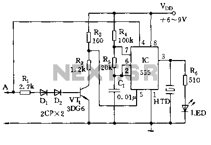
The circuit utilizes a 555 timer along with resistors R4, R5, and capacitor C1 configured in a controllable multivibrator mode. This setup forces the reset terminal (pin 4) to a specific state, allowing for control of the external logic...

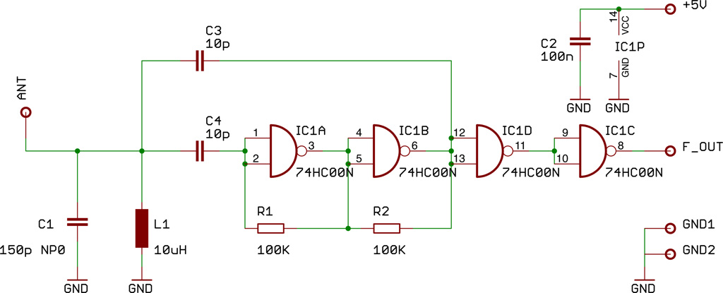
The IR Theremin hardware schematic is notably simple, as the primary input and output devices require minimal connections. This simplicity can be a double-edged sword, as fewer hardware components often lead to increased software complexity. The main components utilized...
This document presents a compact Theremin module designed to connect to an Arduino board, which outputs sound to a speaker or generates control signals such as MIDI or servo commands. The device serves not only as a musical instrument...
Two identical integrated circuits, U1 and U2, known as "hex inverters," are utilized for the primary functions of the theremin. These are CMOS (Complementary Symmetry Metal Oxide Semiconductor) devices commonly employed in digital circuits to perform a logic function...
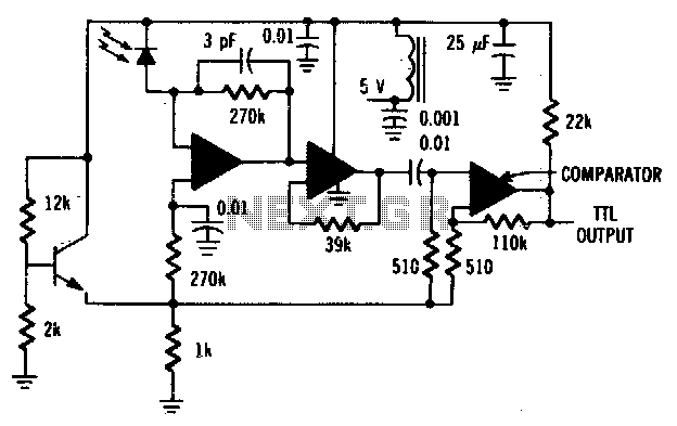
The MFODllOO PIN diode requires shielding from EMI. The MFODllOO PIN diode is a semiconductor device that operates as a switch or rectifier in various electronic circuits. To ensure optimal performance and reliability, it is essential to provide adequate shielding...
Two identical integrated circuits, U1 and U2, known as "hex inverters" are used for the theremin's primary functions. They are CMOS (Complimentary Symmetry Metal Oxide Semiconductor) devices, typically used in digital circuits to perform a logic function called "inversion."...