
555 tri-state acousto-optical logic circuit
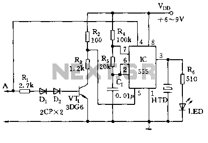
The circuit described operates in a monostable or astable multivibrator configuration, utilizing the 555 timer's ability to toggle between states based on external inputs. The resistors R4 and R5, along with the capacitor C1, define the timing characteristics of the oscillation. In this setup, R4 and R5 are connected in series to control the charge and discharge cycles of C1, ultimately determining the frequency of oscillation. The output frequency can be calculated using the formula for the astable multivibrator configuration:
\[ f = \frac{1.44}{(R4 + 2R5)C1} \]
This equation indicates that increasing the resistance values or capacitance will decrease the frequency, while decreasing them will increase the frequency.
When probe A is floating, the state of VT1 is crucial; it acts as a switch that either allows or blocks current flow based on the logic level detected. This feature allows for the dynamic control of the 555 timer's operation, enabling it to function as an oscillator when needed or remain inactive to conserve power.
The output at pin 3 of the 555 timer drives an LED, which serves as a visual indicator of the circuit's state. When the timer oscillates, the LED blinks at the determined frequency, providing an audible and visual signal to the user. This circuit can be employed in various applications, such as timers, tone generators, and other signal processing tasks where a controllable output is required based on an external logic level.
Overall, this configuration showcases the versatility of the 555 timer in creating responsive and dynamic electronic circuits, allowing for effective control and monitoring of logic states through simple components.As illustrated, 555 and R4, R5, C1 and so connected as a controllable multivibrator mode, which force reset terminal 4 feet to explore pen, control terminal 5-pin external level high and low logic level input related. When the probe A floating, VT1 off, added to 5 feet voltage Vdd, 555 multi-harmonic oscillator circuit can not afford, was 3 feet high, LED light, silent; when the probe A logic "1" VT1 saturated conduction, 5 feet lower than the potential Vdd, 555 oscillation, the oscillation frequency depends on the value of R4, R5 and C1. Oscillation frequency icon parameter is about 1000Hz, audible signal; when the probe A logic "0", 4 feet since the low, 555 is forced to reset, silent and dark.
Related Circuits
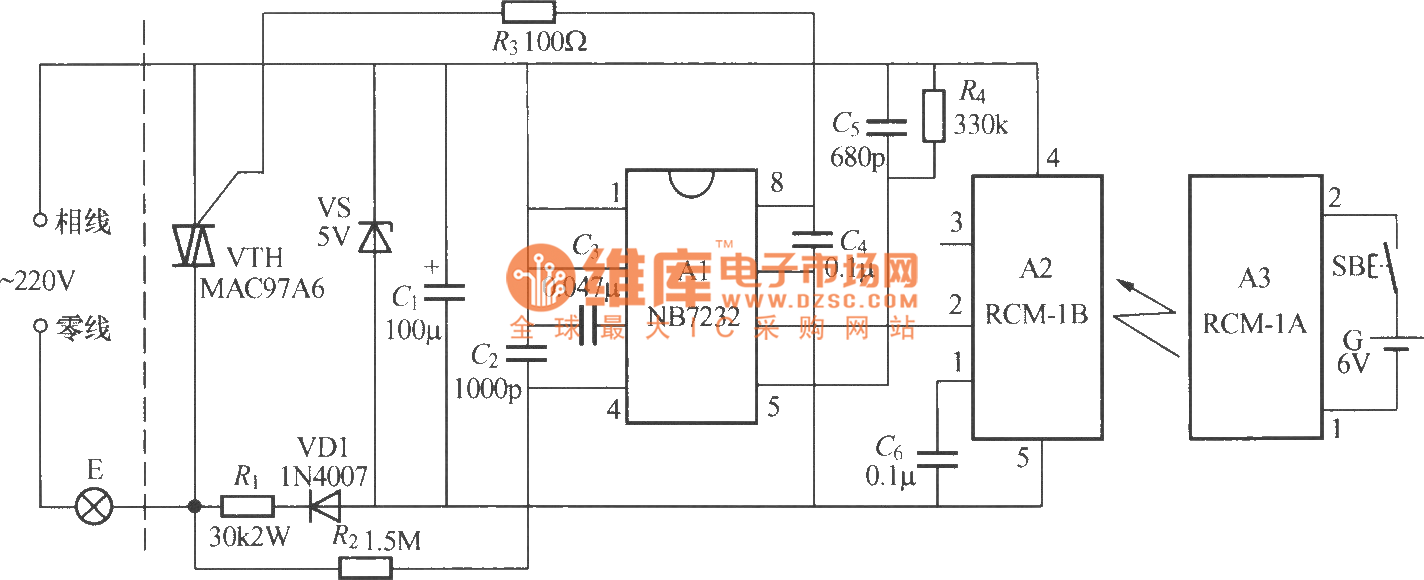
The diagram above illustrates a radio remote control dimmer circuit. This circuit utilizes a micro radio transmit/receive module in conjunction with a light modulation ASIC, resulting in a compact and easily producible design. It operates reliably and features a...
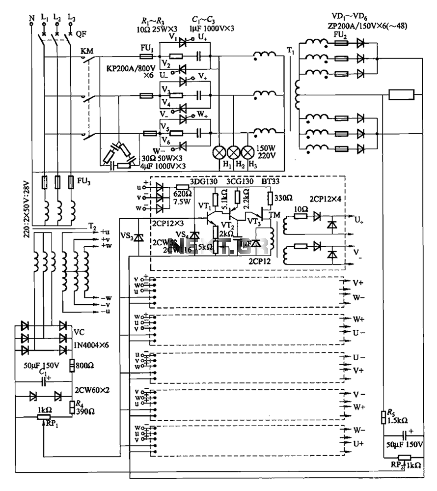
A three-phase thyristor power regulator circuit designed for plating applications, capable of handling currents from 1200A to 6000A at a voltage of 10V. The circuit comprises a main circuit, a trigger circuit, synchronous power components, and a voltage negative...
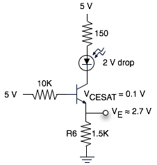
The schematic represents a relatively simple transistor circuit. Analyzing such schematics evokes memories of college days spent studying electrical engineering. However, the complexity of the schematic can be daunting after a long time away from the subject. To refresh...
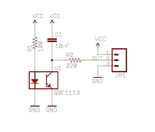
A real-time clock turns off the counter at night to conserve power. When a bee crosses under the LED, the light is reflected back to the sensor, which is a phototransistor, and triggers a digital input to the Arduino...
The first half of the circuit (IC1a) features an input sensitivity of 3 mV and includes a frequency correction network consisting of capacitors C5, C3, and resistors R6 and R8. The bass signal from the phono input is amplified,...

The circuit has four inputs. The voltage gain between each input and the output is maintained at unity by the relative values of the 470 kΩ input resistor and the 470 kΩ feedback resistor. The described circuit operates as a...
Warning: include(partials/cookie-banner.php): Failed to open stream: Permission denied in /var/www/html/nextgr/view-circuit.php on line 713
Warning: include(): Failed opening 'partials/cookie-banner.php' for inclusion (include_path='.:/usr/share/php') in /var/www/html/nextgr/view-circuit.php on line 713