
Optical Theremin

The optical Theremin circuit employs LDRs to modulate both the pitch and volume of sound generated by the oscillator. The operation of the circuit is based on the principle that the resistance of LDRs decreases with increasing light intensity. This characteristic is exploited to create an interactive musical instrument that responds to the proximity and movement of the user's hands, which can be illuminated by a light source.
In the schematic, the oscillator typically consists of a configuration of transistors or operational amplifiers arranged to produce a continuous waveform, such as a sine, square, or triangle wave. The frequency of this waveform is influenced by the resistance of the LDRs, which are strategically placed within the circuit to detect changes in light levels. As the user moves their hand closer or farther from the light source, the amount of light hitting the LDR changes, thus altering the resistance and consequently the frequency of the oscillator.
Additionally, the volume control is similarly managed through another LDR, allowing for a dynamic range of sound output. The output of the oscillator can be connected to a speaker or an audio output jack for sound production. The circuit may also include passive components such as capacitors and resistors to stabilize the oscillation and filter the output signal.
This optical Theremin circuit offers a unique approach to electronic music creation, combining light sensing technology with traditional Theremin functionality, allowing for expressive and innovative sound manipulation based on user interaction. The schematic diagram serves as a visual guide for the construction and understanding of the circuit's operation.A Theremin circuit shown in the schematic diagram below use different method to control the pitch. The oscillator of this tone generator, both the volume and frequency are controlled using LDRs, a light sensitive electronic component, so we can call this circuit an optical Theremin. Look at the following schematic diagram: 🔗 External reference
Related Circuits
The smooth, haunting sounds produced by the Theremin create a mysterious atmosphere. Although its tones are unusual and eerie, the internal circuitry of this electronic instrument is straightforward. The Theremin generates an electromagnetic field using a vertical metal rod...
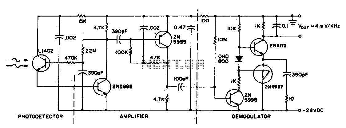
This circuit consists of an L14G2 detector, two stages of gain, and an FM demodulator. Better sensitivity can be obtained using more stages of stabilized gain with automatic gain control (AGC). The circuit design features an L14G2 detector, which serves...
The primary function of the optical receiver is to extract information encoded on a modulated light carrier from a distant transmitter and restore it to its original form. A typical through-the-air communications receiver can be divided into five distinct...
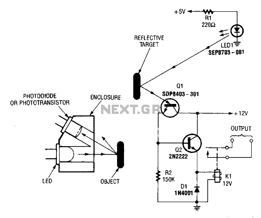
A reflex isolator detects the presence of an object by reflecting light from the object back to the sensor. This technique is effective when an object is in close proximity to the sensor. Reflex isolators, also known as proximity sensors,...

The 203 Theremin employs Wien-bridge oscillators in a heterodyne configuration to create an audible tone that varies with hand position. It operates on a 9-volt battery, ensuring convenience and safety within a compact enclosure. This instrument is a pitch-only...
Using dual flip-flop IC CD4027 employ a 555 based monostable circuit to supply input clock pulses. The circuit described here obviates this requirement. One of the two flip-flops within IC CD4027 itself acts as square wave shaper. The circuit utilizes...