
optical theremin

The optical Theremin's circuitry harnesses the principles of capacitance and light detection to produce sound. The electromagnetic field generated by the metal rod and loop in a traditional Theremin is replaced by the light-sensitive properties of the phototransistors in the optical variant. Each phototransistor is configured with a specific resistor and capacitor to create a unique response curve, enabling the manipulation of sound characteristics. The integration of the 555 timer chip enhances the circuit's capability to amplify the signals generated by the phototransistors, ensuring that fluctuations in light intensity translate into audible variations in pitch and volume.
The choice of phototransistors sensitive to infrared light is crucial for the performance of the optical Theremin, as it directly influences the instrument's responsiveness to different light sources. The construction process involves careful attention to the layout of components on the PCB to minimize noise and interference, which can affect sound quality. Testing and troubleshooting are essential steps in the development of the circuit, ensuring that all connections are secure and that the components function as intended.
In summary, the optical Theremin represents an innovative adaptation of a classic electronic instrument, utilizing light-sensitive components to create a unique sound experience. Its design and functionality showcase the intersection of electronics and musical expression, providing an engaging platform for experimentation and creativity.The hauntingly smooth moaning sounds of the Theremin create a dreadfully mysterious atmosphere. Though its tones are strange and eerie, the inner workings of this electronic instrument are neither strange nor mysterious. The circuitry within a Theremin induces an electromagnetic field in a vertical metal rod and a horizontal metal loop.
The player moves his hand closer to the rod in order to increase the pitch and moves the other hand closer to the loop in order to increase the volume of the note. The hand within the field acts like one plate in a variable capacitor. The rod acts like the second plate in the capacitor system. In an optical Theremin, the rod and loop are replaced by two phototransistors. One phototransistor controls the volume, and the other phototransistor controls the pitch of the output sound.
Unlike the standard Theremin, an optical Theremin relies on photons completing the circuit, rather than variable capacitance. A phototransistor acts just like a normal transistor, but the base current is provided by the incoming photons.
Now that photons are inducing a current flow through the phototransistors, there is now current flowing through the circuit. As the intensity of the light hitting the phototransistors increases, the current through the system also increases.
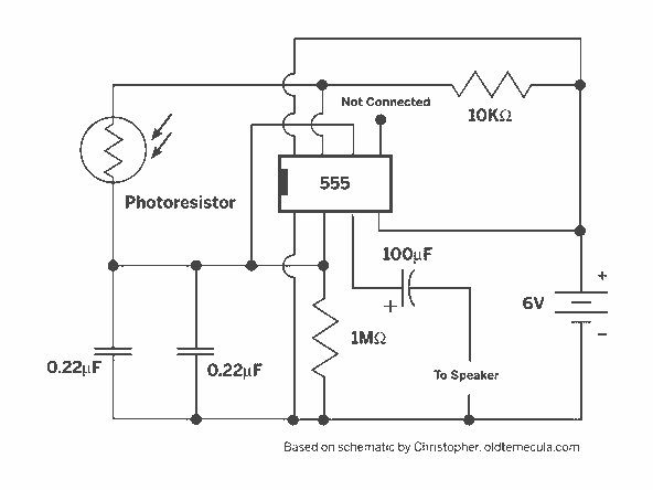
This results in increased volume and pitch from the speaker. If no light hits the phototransistors, then there is no current flow, and the speaker will not produce any sound. I used a circuit diagram which a Theremin enthusiast posted online. Based on his schematics, I purchased the resistors, capacitors, phototransistors, and timing chip necessary to build this circuit from scratch.
Below is the circuit diagram for my optical Theremin courtesy of. The circuit uses a 555 8-pin timing chip. An IC timer chip is an operational amplifier which has a different function than the standard 741 op-amp. Figure 3 is the pin-out diagram for a 555 timing chip (courtesy of RadioShack packaging). Each phototransistor is linked with its own resistor and capacitor. The phototransistor/resistor/capacitor combination, in conjunction with the timing chip, acts like an amplifier.
Since the values for the capacitors and resistors vary between the two phototransistors, each phototransistor has a different range and controls a different function of the optical Theremin. One phototransistor controls the volume, and the other phototransistor controls the pitch. The base current of each phototransistor is provided by the light input. The phototransistors I used are more sensitive to wavelengths of light in the infrared region, which is why this optical Theremin is much louder and higher pitched under an incandescent light bulb (which produces lots of infrared light) than under fluorescent light or sunlight.
I began building this circuit by laying it out on a bred board. I had difficulty getting the device to do little more than squeal one soft, high-pitched noise that did not vary. Later, I found the problem was one missing jumper. Once bred board testing was complete, I soldered the circuit together on a small pc board and succeeded in scaring the living daylights out of everyone in the lab.
This optical Theremin works very well and is very loud; considering it is only powered by four double A batteries and hooks up to a cheap, paper speaker. A photo of my completed circuit is here: Optical Theremin Circuit. After days of work and silly errors, I was able to build a working optical Theremin. This device is not performance worthy; however, it shall prove to be a fun toy, and will be very useful in practical joking fellow students and siblings.
I had fun building it anyway. Here is a link to my video post with this Theremin: Optical Theremin in Action. 🔗 External reference
Related Circuits
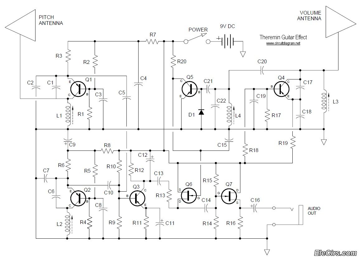
Below is the circuit diagram for the Theremin music instrument effect. A guitar or instrument amplifier is an ideal companion for the Theremin, allowing for bass or treble boost as desired, as well as fuzz (distortion) or reverberation if...
The parts list referenced is from the first page of a Make Magazine article. This list is intended for a harp that utilizes six lasers, so most quantities can be simplified to one. The schematic design based on the described...
When the phototransistor is struck by infrared (IR) light, it begins to conduct, causing the voltage across a 1 MΩ resistor (chosen arbitrarily) and the phototransistor to drop from VCC to lower values. When this voltage falls below VCC/3,...
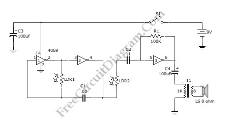
A Theremin circuit is illustrated in the schematic diagram below, utilizing various methods to control pitch. The oscillator of this tone generator allows both volume and frequency to be adjusted using LDRs (Light Dependent Resistors), which are light-sensitive electronic...
A light Theremin constructed using an oscilloscope panel, enhanced with a Joule Thief circuit. The design incorporates a 10 K variable resistor for pitch control and a 20 K variable resistor for volume control. The circuit is powered by...
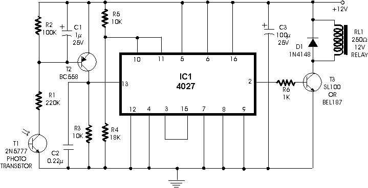
Using dual flip-flop IC CD4027 employ a 555 based monostable circuit to supply input clock pulses. The circuit described here obviates this requirement. One of the two flip-flops within IC CD4027 itself acts as square wave shaper. The circuit utilizes...