Receiver for 50Khz FM optical transmitter
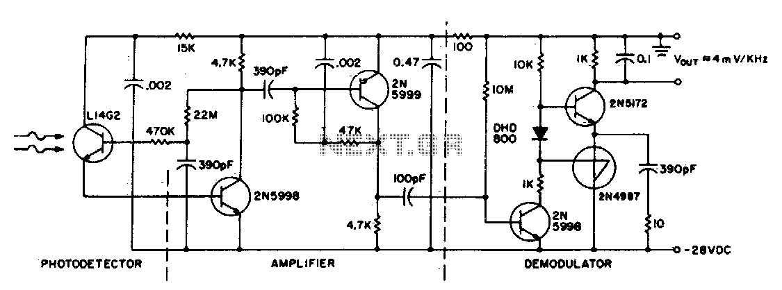
This circuit consists of an L14G2 detector, two stages of gain, and an FM demodulator. Better sensitivity can be obtained using more stages of stabilized gain with automatic gain control (AGC).
The circuit design features an L14G2 detector, which serves as the primary component for signal detection. This detector is known for its capability to process weak signals effectively. Following the detection stage, the circuit includes two stages of amplification, which are crucial for increasing the signal strength to a usable level. Each amplification stage is designed to provide a specific gain, ensuring that the signal remains within optimal levels to prevent distortion.
The FM demodulator is integrated into the circuit to convert the frequency-modulated signal back into its original audio or data format. This process is essential for applications in communication systems where the transmission of information occurs over radio frequencies.
To enhance the sensitivity of the circuit, the implementation of additional stages of stabilized gain is recommended. The use of automatic gain control (AGC) can further improve the performance by automatically adjusting the gain levels based on the input signal strength. This ensures that the circuit maintains consistent output levels despite variations in signal amplitude, thereby improving the overall reliability and clarity of the received signals.
In summary, this circuit configuration effectively combines detection, amplification, and demodulation processes, with the potential for enhanced sensitivity through the incorporation of AGC and additional gain stages.This circuit consists of a L14G2 detector, two stages of gain, and a FM demodulator Better sensitivity can be obtained using more stages of stabilized gain with AGC.
