
optically coded key
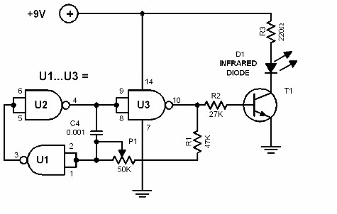
The optical key system operates on the principle of infrared communication, utilizing a transmitter and a receiver to facilitate the unlocking of doors. The transmitter module (Diagram 27.0) is designed to emit an infrared beam that is modulated at a specific frequency. This modulation can be fine-tuned using a potentiometer labeled P1, allowing for customization based on environmental factors or interference from other IR sources.
The receiver module (Diagram 27.1) incorporates a phototransistor, which is sensitive to the IR light emitted by the transmitter. When the transmitter sends out its modulated signal, the phototransistor captures this signal. The receiver is equipped with a frequency comparator circuit that continuously monitors the modulation frequency of the incoming IR beam. If the frequency of the received signal matches the pre-set internal frequency of the receiver, it triggers a relay mechanism.
The relay serves as an electronic switch that can control various types of electric door locks, enabling the opening or closing of the lock based on the successful detection of the correct IR signal. This system is particularly advantageous for security applications, as it allows for keyless entry while minimizing the risk of unauthorized access. The design can be further enhanced with additional features such as encryption for the transmitted signal, making it more secure against potential interception or duplication of the IR signal.
Overall, the optical key system provides a reliable and efficient method for controlling access to secured areas through the use of infrared technology, combining ease of use with advanced security features.The optical key works as an infrared door opener for house, garage and the likes. Diagram 27. 0 functions as the key. It is a transmitter module which sends out a modulated infrared (IR) beam. The modulating frequency can be adjusted through P1. Diagram 27. 1 is the actual lock (receiver module). It uses a phototransistor to receive the IR beam comi ng from the key transmitter module. It compares the modulation frequency of the transmitter beam to its internal frequency. When the two frequencies match, the relay is activated, thereby opening whatever elecric door lock is connected to it. 🔗 External reference
Related Circuits
This simple circuit is the electronic version of the combination lock. Using the special purpose LS7220 digital lock IC, the circuit allows a 4 digit combination of your choice to activate a relay for a set period of time....
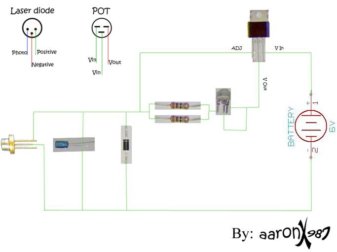
A new user expresses interest in lasers and has purchased an inexpensive red laser pointer and LED light combination keychain. The red laser pointer and LED light combination keychain is a compact and versatile device that serves multiple functions. The...
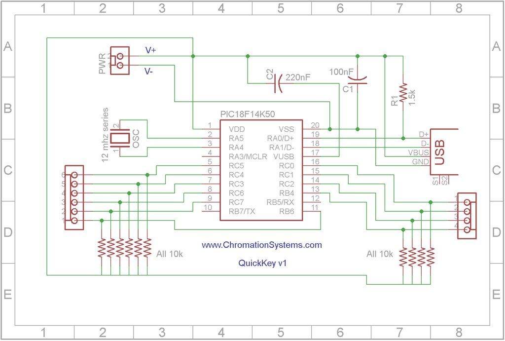
Quick Key Adapter, 10 Button HID Keyboard. This document outlines the process of creating a USB-connected Human Interface Device (HID) keyboard featuring 10 button inputs. The Quick Key Adapter is designed to facilitate user interaction through a compact keyboard interface....
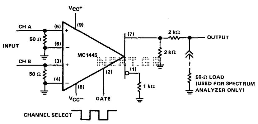
Apply a signal to each differential amplifier input pair. When the gate voltage changes from one extreme to the other, the output can alternate between the two input signals. When the gate level is high (1.5 V), a signal...
Most of the source code for this project is based on the Telecard reader project from my website. The components are few and ordinary, which means they are low-cost and easy to find. The "keys" are empty or non-telecards...
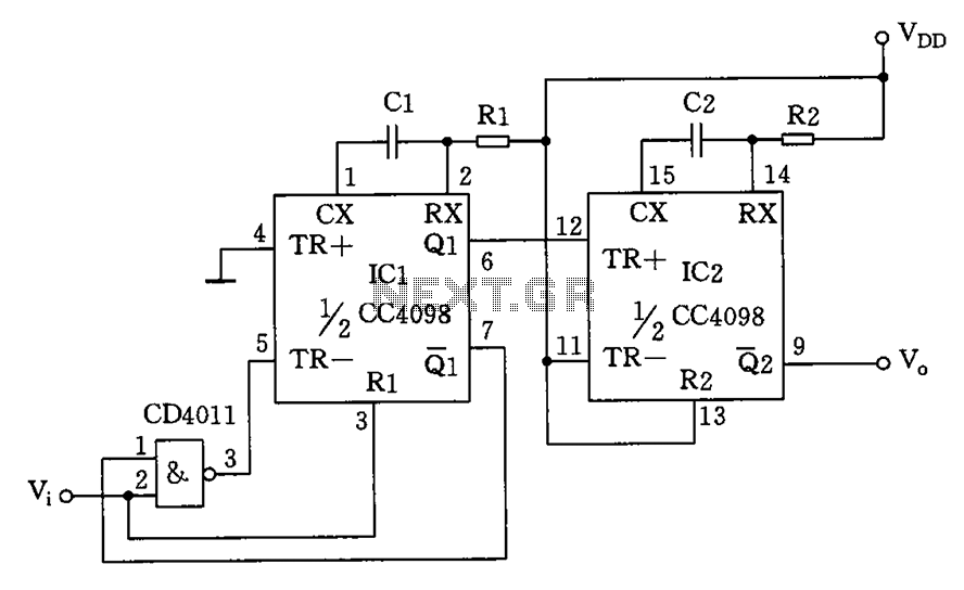
The circuit depicted features a double oscillator utilizing a monostable multivibrator CC4098 and a quad 2-input NAND gate CC4011, among other components. This circuit allows for adjustable frequency and duty cycle. It is primarily designed as a keying oscillator,...