
Keying oscillator circuit

The described circuit employs the CC4098, a versatile monostable multivibrator, which is pivotal for generating a single output pulse in response to a triggering input. The duration of this pulse can be adjusted by varying the external resistor and capacitor values connected to the CC4098, thus allowing for customization of the output signal's timing characteristics. The CC4011 NAND gates are configured to create an oscillator circuit that can be tuned to the desired frequency range. By adjusting the feedback and timing components, the oscillation frequency can be modified, providing flexibility in the signal generation process.
The combination of the CC4098 and CC4011 enables the creation of a keying oscillator that can produce a low-frequency square wave signal. This signal is useful in various applications, such as driving other circuits, modulation, or as a timing reference. The circuit's ability to adjust both frequency and duty cycle makes it suitable for applications requiring different signal characteristics without the need for complex modifications.
In summary, this circuit design effectively integrates a monostable multivibrator and NAND gates to create a flexible low-frequency signal generator, emphasizing ease of use and adaptability for various electronic applications. Circuit as shown by the double oscillator is keyed monoflop CC4098, Quad 2-input NAND gate CC4011 and other composition. The circuit is the frequency and duty cycle adjustable keying oscillator constituted by a single-shot, mainly for less precision low-frequency signal generator.
Related Circuits
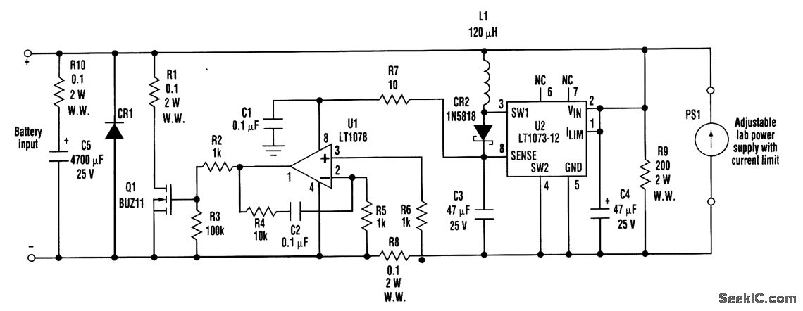
When developing a battery charger, using a real battery can be impractical. The battery simulator circuit described here serves as an alternative. The positive and negative terminals of the battery input should be connected in place of the actual...
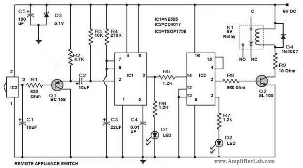
The circuit diagram of a remote-controlled appliance switch circuit includes two main components: IC1 (NE 555) and IC2 (CD 4017). The remote-controlled appliance switch circuit is designed to allow users to control electrical appliances wirelessly. The heart of this circuit...
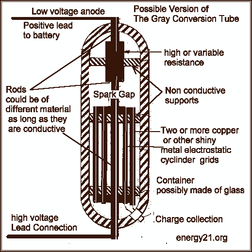
This type of design can produce a very high amperage current for a fraction of a second that can be used to do some useful work if properly harnessed. A point to remember is that Paul Baumann built his...
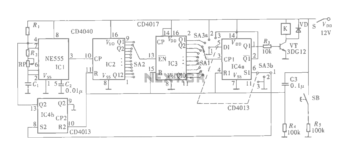
The multifunction circuit primarily refers to its capability to operate in three modes: "delayed pull," "time release," and "delayed cycle." The term "delay" indicates that the relay is energized after a predetermined time; however, the relay does not activate...
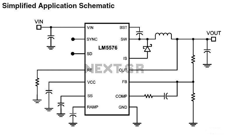
LM5576MHX absolute maximum ratings: (1) VIN to GND: 76V; (2) BST to GND: 90V; (3) PRE to GND: 76V; (4) SW to GND (Steady State): -1.5V; (5) BST to VCC: 76V; (6) SD, VCC to GND: 14V; (7) BST...
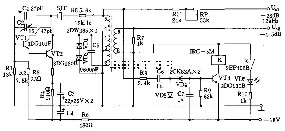
The circuit depicted is a 12 kHz intermediate frequency oscillator designed for an alarm system. It employs a variable feedback oscillation circuit where the oscillation frequency is primarily determined by a quartz crystal. Capacitors C1 and C2 are used...