
Optocoupler circuits
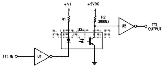
The TTL-to-TTL isolator circuit utilizes a single open-collector TTL inverter (U1) to achieve signal isolation between two TTL logic levels. The open-collector configuration allows the inverter to pull the output low when the input signal is high, effectively creating a low output state. This output state is used to control an LED, where the cathode of the LED is connected to the output of the inverter.
In this configuration, when the input to the inverter is at a high logic level (typically 2.4V to 5V for TTL), the output of U1 transitions to a low state (approximately 0V). This low state connects the cathode of the LED to ground, allowing current to flow from the anode of the LED through a current-limiting resistor to the positive supply voltage. Consequently, the LED illuminates, providing a visual indication of the high input signal.
The circuit can be enhanced by including a current-limiting resistor in series with the LED to prevent excessive current flow, which could damage the LED. The value of this resistor can be calculated based on the forward voltage drop of the LED and the supply voltage. Additionally, the circuit can be designed to accommodate various input and output voltage levels by selecting appropriate components that match the desired specifications of the application.
Overall, this TTL-to-TTL isolator circuit serves as an effective method for isolating different stages of digital circuitry while providing a clear visual indication of the input signal state through the LED. This circuit is a TTL-to-TTL isolator circuit. The driver circuit is an open-collector TTL inverter (Ul). When the input is high, then the output of the inverter is low. Thus, when the input is high, the output of Ul grounds the cathode end of the LED and causes the LED to turn on. 🔗 External reference
Related Circuits
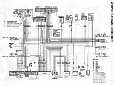
The following circuit illustrates the electrical circuit diagrams for the Toyota Supra. The diagrams indicate the point at which the power source is received. The electrical circuit diagrams for the Toyota Supra provide a comprehensive overview of the vehicle's electrical...
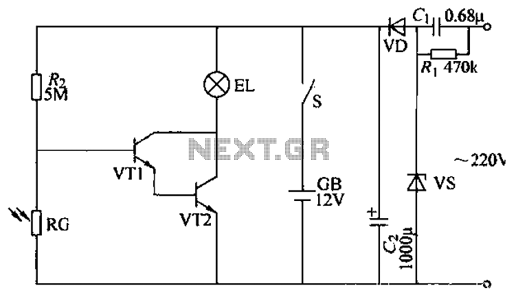
The power supply circuit features a step-down capacitor (C1), bleeder resistors (R), a Zener diode (VS), a full diode (VD), and a filter capacitor (G), along with switches and batteries (GB, SC). The light control circuit is composed of...
Several schematic drawings of battery charger circuits are provided. These circuits cover 5W to 200W for NiCd, NiMH, Lead-Acid, Li-Ion/Polymer, and LiFePO4 battery packs. The charger circuit files aim to assist users in selecting the appropriate chargers and to...
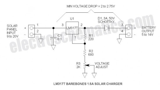
This is a simple and cost-effective solar battery charger that can be constructed by hobbyists. It has some limitations compared to other similar controllers, but it also provides several benefits. While primarily designed for charging lead-acid batteries, it can...

This topic will be locked and will display all of the circuits and some photos of the devices being worked on in the Joule Thief topic. This process will take some time, so patience is appreciated. If any errors...
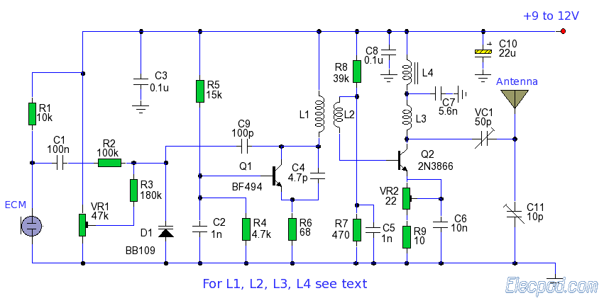
The ZN414 is an economical, single-chip AM radio integrated circuit introduced in 1972 by Ferranti. The TDA7000 is a monolithic integrated circuit designed for mono FM portable radios or receivers, focusing on minimizing size. Additionally, there is an FM...