
Nightlight lighting circuits

The power supply circuit is designed to convert high voltage AC to a stable low voltage DC, suitable for powering electronic components such as EL lamps. The step-down capacitor (C1) is crucial for reducing the voltage while maintaining the necessary current flow. The bleeder resistors (R) ensure that the circuit discharges properly, preventing any potential buildup of voltage that could damage sensitive components. The Zener diode (VS) plays a critical role in voltage regulation, providing a stable reference voltage to safeguard the circuit against fluctuations in the input voltage.
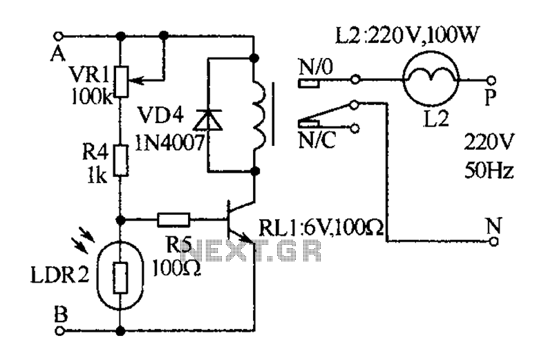
In the light control circuit, the photoresistor (RG) is a key component that varies its resistance based on ambient light levels. During daytime conditions, the low resistance of RG keeps transistors (VT1 and VT2) off, preventing current flow to the EL lamp. This feature is essential for energy conservation, as it ensures that the lamp only operates when necessary. Conversely, at night, the increasing resistance of RG allows the voltage to rise above the threshold of 1.4V, triggering the saturation of the transistors. This transition results in the EL lamp being powered on, providing illumination when it is most needed.
The AC input is first processed by the capacitor (Ci), which acts as a filter to smooth out the AC waveform before it is rectified by the diode (VD). The filter capacitor (Cz) further stabilizes the output by reducing ripple voltage, ensuring that the DC supply remains consistent for the EL lamp operation. The entire circuit is designed with efficiency and reliability in mind, making it suitable for applications where automatic light control is desired, such as in outdoor lighting systems or nightlights. Each component has been selected to optimize performance while maintaining safety and durability in varying environmental conditions. Circuit, power supply circuit consists of step-down capacitor c1, bleeder resistors R, Zener diode vs, the entire diode VD and filter capacitor G, switches and batteries GB s c omposition; light control circuit consists of resistors R2, photoresistor RG and the transistor VT1, VT2 composition. AC 220V voltage by Ci buck, vs regulator, VD rectifier and Cz filter, so as to provide DC 12V EL lamp and light control circuit voltage, but also by S GB of charge.
During the day, RG affected by light exposure to the low resistance state, VT1 and VT2 off, EL does not shine. Night, RG becomes high impedance state, the voltage across voltage higher than 1. 4V, so that VT1 and VT2 saturated conduction, EL energized to emit light. Nightlight kind shown in Figure
Related Circuits
The receiver, as depicted in the figure, assists patients in avoiding missed audio signals during the daytime. The receiver operates independently, and the lighting will automatically turn off. At night, the lighting signal receiver activates simultaneously with the patient's...
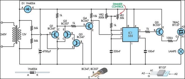
This circuit serves as the foundation for the dimmers in a model theatre lighting system that utilizes touch globes as the light source. The circuit is centered around a 55. This circuit design incorporates a dimmer functionality specifically tailored for...
This simple water detector circuit utilizes alternating voltage to prevent electrode corrosion. It is easy to construct and employs N1 as a trigger Schmitt gate to generate the AC signal. When a conductive substance, such as an aqueous solution,...

The Switchgate is a simple dual gate circuit based on a 556 timer configured in monostable mode, featuring a trigger input that activates two switches. The outputs of the monostables are also available individually. Recent research has led to...
This is a constant current source using a FET. It serves as a simple replacement for a series resistor to limit current. The N-Channel FET BF256C can provide a current of 15mA. Before using integrated circuits, it is advisable...
The frequency of a crystal-controlled oscillator is maintained with high precision through the use of a quartz crystal. The frequency is primarily determined by the dimensions of the crystal, particularly its thickness, while other circuit parameters have minimal impact....