
1.5V-powered microphone signal amplifying circuit
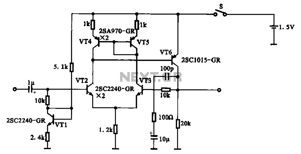
This 1.5V-powered microphone signal amplifying circuit operates by utilizing a series of transistors to amplify audio signals captured by a microphone. The circuit begins with the microphone, which converts sound waves into a small electrical signal. This signal is then fed into the base of the differential amplifier formed by VT2 and VT3. The differential amplifier is crucial for enhancing the signal-to-noise ratio by amplifying the desired audio signal while rejecting common-mode noise.
Transistor VT6 acts as a common emitter amplifier, further increasing the signal strength. The output from VT6 is connected to the collector, which provides a higher voltage swing, resulting in a more robust output signal that can drive subsequent audio processing stages or output devices.
The configuration of VT1 and VT2, where their collector and base are short-circuited, allows for a stable DC biasing condition necessary for proper transistor operation. This setup ensures that the transistors operate within their active region, providing linear amplification of the input signal.
The emitter resistors, formed by VT4 and VT5, play a significant role in stabilizing the bias point of the circuit. They help to set the operating point of VT2 and VT3, ensuring consistent performance despite variations in temperature or supply voltage.
Overall, this circuit exemplifies an efficient design for low-voltage microphone signal amplification, leveraging the properties of transistors to achieve significant amplification while maintaining low power consumption. The careful selection of components and their configuration is vital for achieving the desired audio fidelity and performance.1.5V-powered microphone signal amplifying circuit 1.V power supply shown for the microphone signal amplifying circuit, which by VT2, VT3 differential amplifier is constituted o f the main group into a part, VT6 a common emitter voltage of the amplifier, the output signal is amplified by the collector. Input by the input signal VI2 base electrode, the collector and base of VT1 VT2 short-circuits to the base of a DC bias, VT4, VT5 the emitter resistor circuit composed of VT2, VT3 collector-bias.
Use transistor may reduce the resistance power loss can be obtained the desired amplification effect.
Related Circuits

This circuit exhibits an exceptionally fast high-frequency response, as demonstrated by applying a 100 kHz square wave to the input. All graphs were produced using Tina Pro. The circuit's design is optimized for high-frequency applications, showcasing rapid response times that...
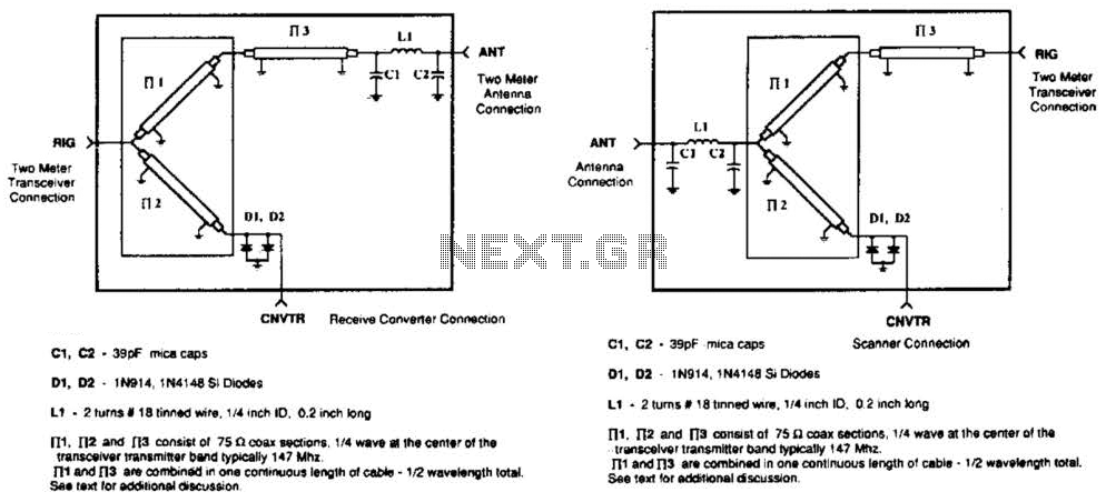
A pair of diodes and a quarter-wave transmission line are utilized as an automatic TR switch. D1 and D2 conduct during transmit periods, short-circuiting the scanner input. In this mode, the quarter-wave line appears as an open circuit. In...
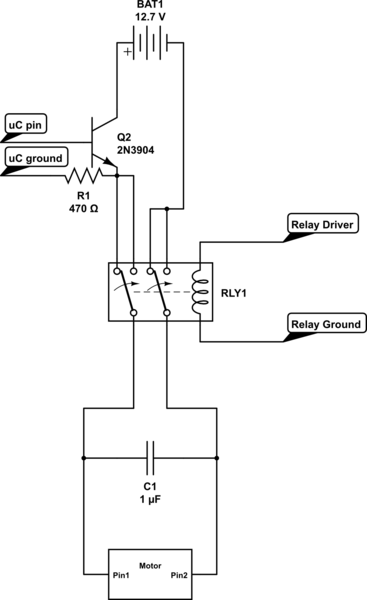
Control the state (on/off) and direction of two linear actuators that are essentially DC motors. The linear actuators operate at 12VDC and draw 10 amps of current at full load. A 25A external power supply has been purchased, as...
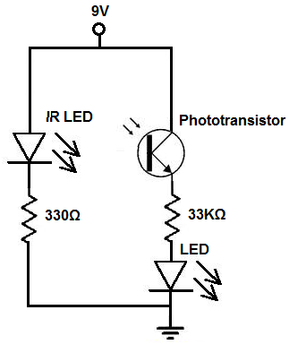
There are two methods to construct a proximity detector. The first method involves mounting the infrared (IR) LED and the phototransistor so that they face each other. In this configuration, the infrared light emitted by the IR LED is...
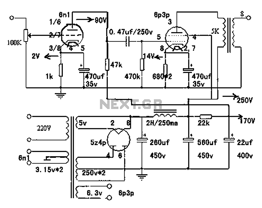
Electronic tube amplifier enthusiasts consider a simple, high-quality single-ended Class A circuit to be an ideal starting point. This single-ended Class A tube amplifier is known for its warm sound and high success rate. The article outlines the use...
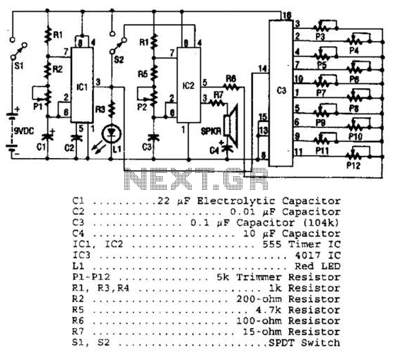
Three integrated circuits (ICs) are utilized to generate sounds. IC1 is a 555 timer configured as an astable multivibrator, producing clock pulses. The frequency of these clock pulses is adjustable via a trimmer potentiometer, P1. These clock pulses are...