
Control Circuits
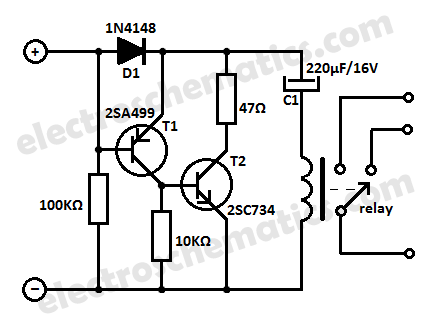
The low current relay circuit is particularly suitable for applications where power efficiency is critical, such as in portable devices powered by batteries. The bistable relay allows the circuit to maintain its state without continuous power, significantly reducing the overall current consumption. By integrating additional components, such as resistors and capacitors, the relay can be configured to respond to input signals in a manner similar to a monostable relay, providing a temporary output state before returning to its default state.
The wireless keylogger project is designed for ease of assembly and use. The logging unit captures keystrokes and transmits the data wirelessly to the USB receiver, which connects to a host computer. The 2.4GHz frequency band is chosen for its balance of range and interference resistance, making it suitable for indoor applications. The keylogger's firmware is programmed to handle data encoding and transmission, ensuring that keystrokes are logged accurately and efficiently.
The PCB design is optimized for compactness and functionality, allowing for easy integration into various devices. The project documentation includes detailed schematics that illustrate the connections between components, as well as layout designs for manufacturing the printed circuit board. The software provided enables users to configure the keylogger settings and retrieve logged data from the receiver.
Overall, this combination of a low current relay circuit and a wireless keylogger presents a versatile solution for applications requiring discreet monitoring and efficient power usage. The design and implementation details provided in the project documentation facilitate successful replication and deployment of the system in various electronic devices.This low current relay circuit is designed to be used in battery operated electronic devices. Its operating current is in micro amperes ( µA). This is done by using a bistable relay and adding some components to force the relay to behave like a monostable relay. Read more » This is a do it yourself wireless hardware keylogger project, consisting of a logging unit with a 2. 4GHz transmitter, and a USB-based receiver. The project includes the schematics, PCB design, firmware, software and lots of additional files and data. A wireless keylogger is a perfect solution for monitoring user activity, at very low risk of disclosure, is a purely electronic device, so no access to the operating system is required.
The Wireless Keylogger consists of two main building blocks: the transmitter, and the receiver. The actual keylogging takes place in the transmitter, which is in fact a PS/2 hardware keylogg. Read more » 🔗 External reference
Related Circuits
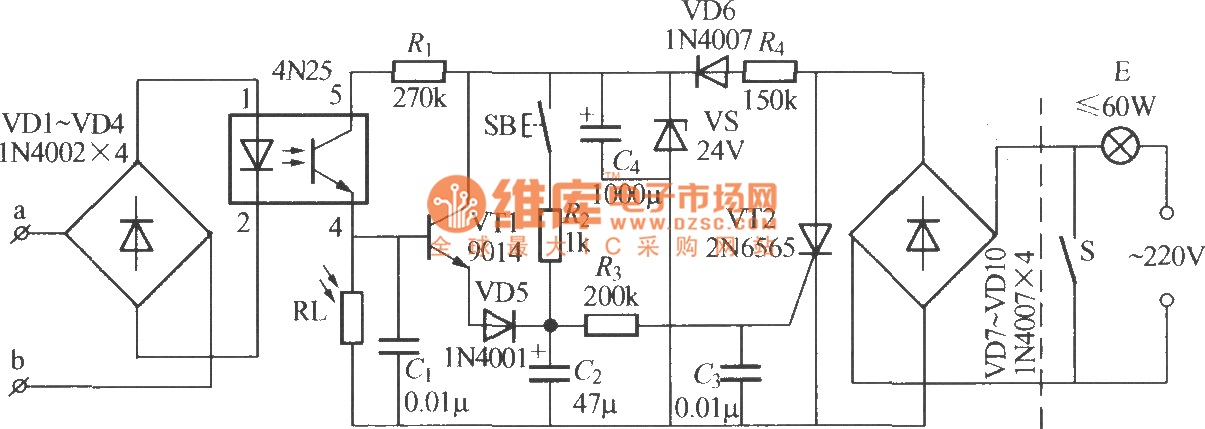
The diagram illustrates an automatic lighting control circuit activated by a telephone. At night, when the telephone rings or the user picks up the receiver, the light turns on. If the telephone stops ringing (when no one is listening)...
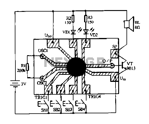
Constantly changing light and sound analog controller circuit 04 The circuit designated as the "Constantly Changing Light and Sound Analog Controller Circuit 04" is designed to modulate both light and sound outputs in a dynamic manner. This type of...
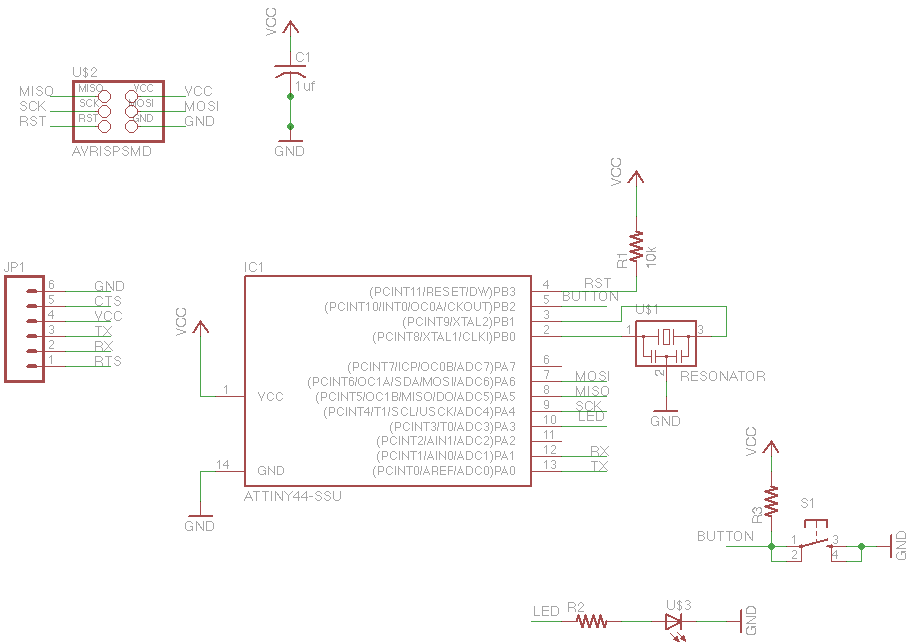
For this week's assignment, a chip design was provided, and the task was to incorporate a button and an LED (light-emitting diode). The objective was to fabricate the chip and program it to interact with the light and button....
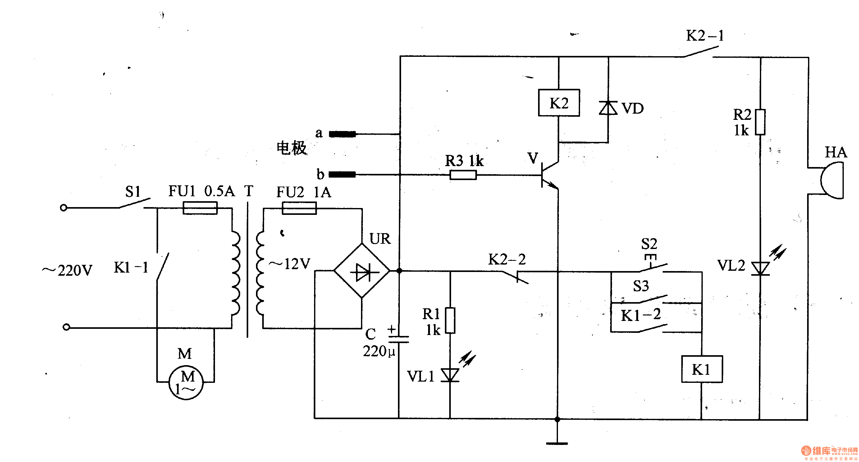
The working principle of the circuit pertains to a medical electric aspirator waterproof controller, which includes a power supply circuit, a liquid level detection control circuit, and an alarm circuit, as illustrated in Figure 9-47. The power supply circuit...
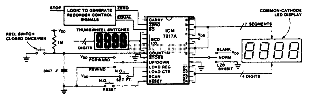
This circuit illustrates various applications of up/down counting for monitoring dimensional position. In the tape recorder application, the LOAD REGISTER, EQUAL, and ZERO outputs are utilized to control the recorder. To ensure the recorder stops at a specific point...
The Olimex P-40 development board will be utilized, though the circuit can also be constructed on a breadboard due to its simplicity. The schematic for the initial implementation of servo control is provided below. Servos, like any motors, can...