
OSCCAL Value Finder Board with 16F88
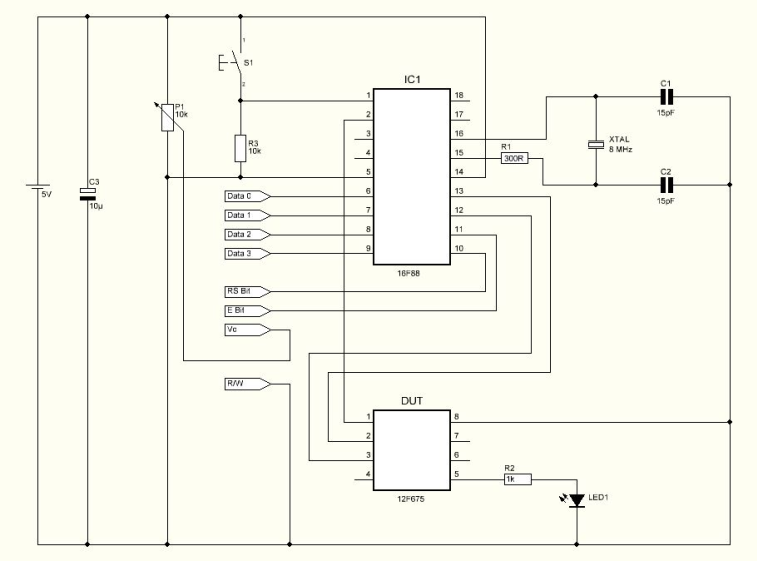
The value displayed is in Hexadecimal format which means it can be used without conversions directly to the device's memory. Turning on the circuit, it will display the name of the project and then it will display the message "Put Pic Hit But". At this point it is possible to place the 12F675 device on the socket and press the push button. Pressing the push button S1, the circuit will start to measure the signal from the 12F675 device and will count the pulses. The display shows the pulse signal being measured and the current Osccal value.
When the pulse sent by the 12F675 device matches the requested pulse length, the circuit will stop the device and display the recommended osccal value. Since the circuit controls the power of the 12F675 device, at this point it is possible to remove the device from the socket and place a new one. Pressing S1, the circuit will start a new test.
This is a very interesting circuit for the microcontroller beginner. Not only for recovering lost osccal values but also to understand some microcontroller characteristics. The crystal must be a good quality crystal or precise results may not be ensured. The circuit uses an 8X2 LCD making it a portable project.
The circuit operates using a PIC12F675 microcontroller, which is a low-power, 8-bit microcontroller with an integrated 10-bit ADC and GPIO ports. The primary function of this circuit is to calibrate the internal oscillator of the PIC12F675 by dynamically adjusting the osccal value until the desired pulse width is achieved.
The GPIO.4 pin is configured as an output, responsible for generating pulses. This pin drives a square wave signal, which is essential for testing the circuit's response. The GPIO.5 pin, configured as an input, receives the feedback pulse from the microcontroller, allowing the circuit to monitor the current osccal value. The internal loop increases the osccal value until the pulse width matches the expected timing.
An 8x2 LCD display is interfaced with the microcontroller to provide user feedback. It initially displays the project name and prompts the user to insert the PIC12F675 into the designated socket and press the button S1. Once the button is pressed, the microcontroller begins measuring the incoming pulses and updates the display with the current osccal value being tested.
The circuit includes a push button switch (S1) that initiates the calibration process. This allows users to easily start new calibration sessions after replacing the microcontroller. The circuit also features a power management system to ensure that the PIC12F675 can be safely removed and replaced without power interruption.
For optimal performance, a high-quality crystal oscillator should be used, as the accuracy of the calibration process heavily relies on the stability of the clock signal. The design is compact and portable, making it an excellent educational tool for beginners in microcontroller programming and calibration techniques.The program loaded in the 12F675 device which has no osccal value will force a pulse on GPIO.4 and it will make a loop while increasing the osccal value internally. GPIO.5 will send the current osccal value used for each pulse sent. Because the device has no calibrated osccal value, the pulse will be variable. The circuit will wait until it receives the correct pulse. When the correct pulse is received, it will stop the test and display the osccal value used when the correct pulse was measured.
The value displayed is in Hexadecimal format which means it can be used without conversions directly to the device?s memory. Turning on the circuit, it will display the name of the project and then it will display the message ? Put Pic ? Hit But ?. At this point it?s possible to place the 12F675 device on the socket and press the push button. Pressing the push button S1 the circuit will start to measure the signal from the 12F675 device and will count the pulses.
The display shows the pulse signal being measured and the current Osccal value. When the pulse sent by the 12F675 device matches the requested pulse length the circuit will stop the device and display the recommended osccal value. Since the circuit controls the power of the 12F675 device, at this point is possible to remove the device from the socket and place a new one.
Pressing S1 the circuit will start a new test. This is a very interesting circuit for the microcontroller beginner. Not only for recovering lost osccal values but also to understand some microcontroller characteristics. The crystal must be a good quality crystal or precise results may not be ensured. The circuit uses an 8X2 LCD making it a portable project. 🔗 External reference
Related Circuits
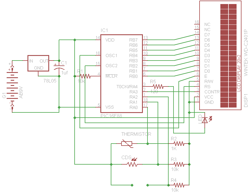
The initial concept for this project involves interfacing the WINTEK WD-C2401P LCD panel with a PIC microcontroller. The intention is to incorporate several ADC readings to provide useful information on the LCD. PORTB on the PIC serves as the...
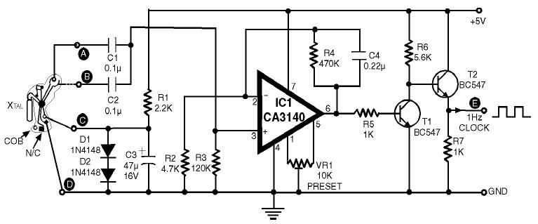
1Hz Clock Generator Circuit with Chip On Board (COB). The COBs used in different watches may differ somewhat in their configuration. However, through trial and error, one can identify the appropriate points corresponding to points A, B, C, and...
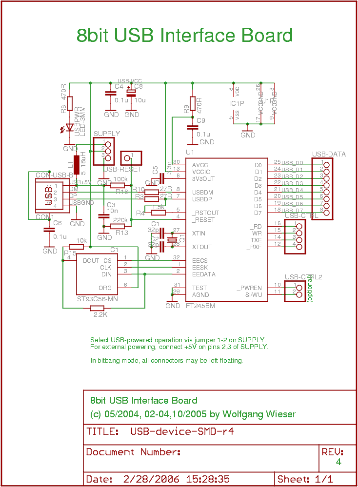
The objective was to create a compact USB interface board that can be easily connected to microcontroller boards. It is designed to support both USB-powered and externally-powered operation. The number of external components has been minimized, although there are...
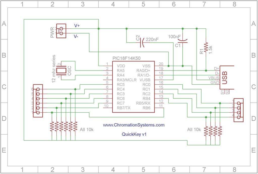
Quick Key Adapter, 10 Button HID Keyboard. This document outlines the process of creating a USB-connected Human Interface Device (HID) keyboard featuring 10 button inputs. The Quick Key Adapter is designed to facilitate user interaction through a compact keyboard interface....
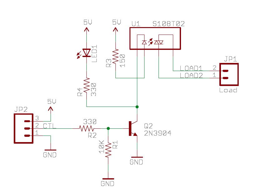
The Sparkfun Solid State Relay (SSR) Breakout Board operates similarly to a traditional relay but utilizes semiconductors for switching. It is powered by the mbed VU 5V supply and is compatible with any mbed digital output pin. The schematic...
A circuit has been identified that integrates a voltage regulator and filter to isolate the voltage supplied by the receiver for powering an operational amplifier (op-amp) that drives a meter. Additionally, the circuit isolates the carrier frequency from the...