
ssr breakout boards
The Sparkfun Solid State Relay Breakout Board is designed for interfacing with microcontrollers such as the mbed, providing a means to control high voltage AC loads safely and efficiently. The integration of the S108T02 Sharp SSR module allows for robust performance in switching applications, with a maximum load capacity of 125VAC at 8A. The board's design incorporates necessary safety features, such as optically isolated control inputs, ensuring that the microcontroller's low voltage side remains isolated from the high voltage load side.
In practical applications, the SSR can be utilized in various automation projects, including home automation systems, lighting control, and industrial equipment management. The use of a transistor driver circuit facilitates the control of the SSR with minimal current draw from the microcontroller, making it suitable for integration into low-power systems.
The implementation of a zero-crossing detection circuit within the SSR aids in reducing electromagnetic interference, which is particularly beneficial in sensitive electronic environments. The absence of mechanical components in the SSR results in faster switching times and increased reliability compared to traditional electromechanical relays.
When deploying the SSR in a circuit, it is pertinent to ensure that adequate heat dissipation measures are in place, especially when operating near the maximum load specifications. The addition of a heat sink is recommended to maintain optimal operating temperatures and prolong the lifespan of the SSR module.
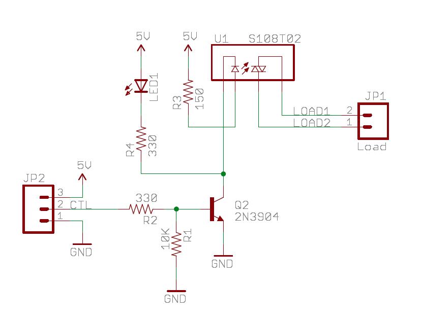
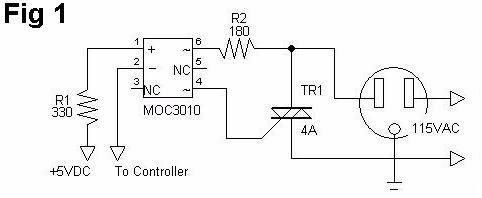
For applications requiring both AC and DC switching capabilities, alternative SSR solutions, such as the Phidgets SSR board, offer versatility with the use of MOSFETs, accommodating a broader range of voltage and current specifications. This flexibility allows designers to select the appropriate SSR based on the specific requirements of their projects, ensuring efficient and safe operation in diverse applications.The Sparkfun Solid State Relay (SSR) Breakout Board is shown below. An SSR works like a relay but is built using semiconductors for switching. It will run off of mbed`s VU 5V supply and works with any mbed digital output pin. The schematic is shown below for the Sparkfun Solid State Relay board seen above. It uses a S108T02 Sharp SSR module and ca n switch 125VAC at 8A (AC only - not DC). Note that it also requires an on-board driver circuit, and the external wire connections are the same as most relay boards. A transistor driver circuit is used to control the SSR module. Any digital out pin can be used to control the SSR (connects to the control input (CTL - JP2-2) of the SSR driver circuit).
The SSR module has a TRIAC output with optically isolated control inputs. A high voltage power line shorted to a digital logic circuit on a breadboard can blow up an entire computer system, or cause electrocution if touched. For safety, keep the wires for any high voltage and/or high current devices well away from the breadboard and do not touch them when power is on.
Even a momentary wire short can blow things ups. An inline fuse and even a GFI breaker is not a bad idea. Long before a standard household AC circuit breaker trips, electronic parts will blow out with a short. Make sure that the bottom side of the PCB does not short out on any metallic surfaces. Breadboard contacts and small jumper wires only handle about one amp. The relay boards typically use screw terminals to attach the larger wires needed for the external device.
Just driving the coil of a large relay requires most of the additional current that can be supplied to mbed via the USB cable, so an external DC power supply will likely be needed to power the relay coils and the load of the external device. For electrical isolation, when using a relay to control external AC devices or high voltage DC devices, do not connect the grounds on the power supplies from the control side to the load side.
For the demo, one of the wires in a 2-wire AC extension cord was cut, pulled apart, stripped back, and each end attached to one of the two black screw terminals used for the load. The lamp was them plugged into the extension cord. In the video above running the demo code, the SSR turns the lamp on and off every 4 seconds. Note the lack of an audible click (unlike a mechanical relay), and the indicator LEDs changing, mbed LED1 and the green LED on the SSR board.
Some SSRs can dim lights, but this one does not have the phase control sense circuit needed. It does have a zero crossing circuit to reduce RF noise emissions. A heat sink for the SSR module is needed at anything near the rated load. The Phidgets SSR board seen below can switch both AC and DC voltages at lower voltage and current levels. It uses a small NEC/CEL SSR IC. Instead of a TRIAC, two MOSFETS are used for switching, so it can switch DC or AC. 🔗 External reference
Related Circuits
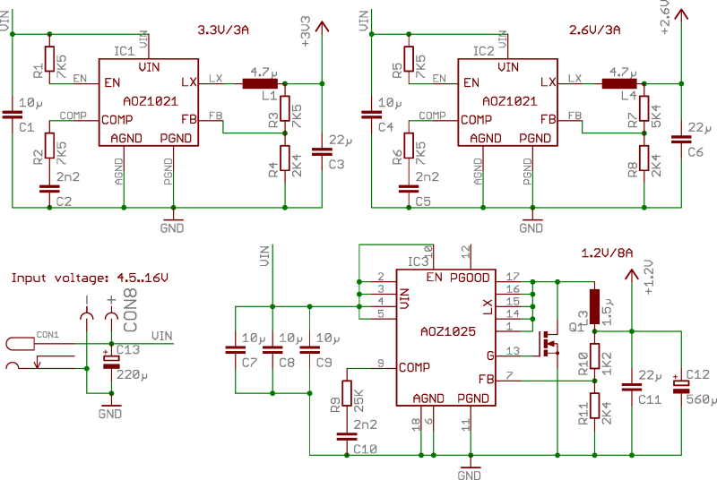
ZTEX USB-FPGA Boards require three different voltages: 1.2V, 2.5V-2.6V, and 3.3V, which must be supplied externally. This can be achieved using Power Supply Modules, Experimental Boards, or a user-specific design. To facilitate development in the latter scenario, three reference...
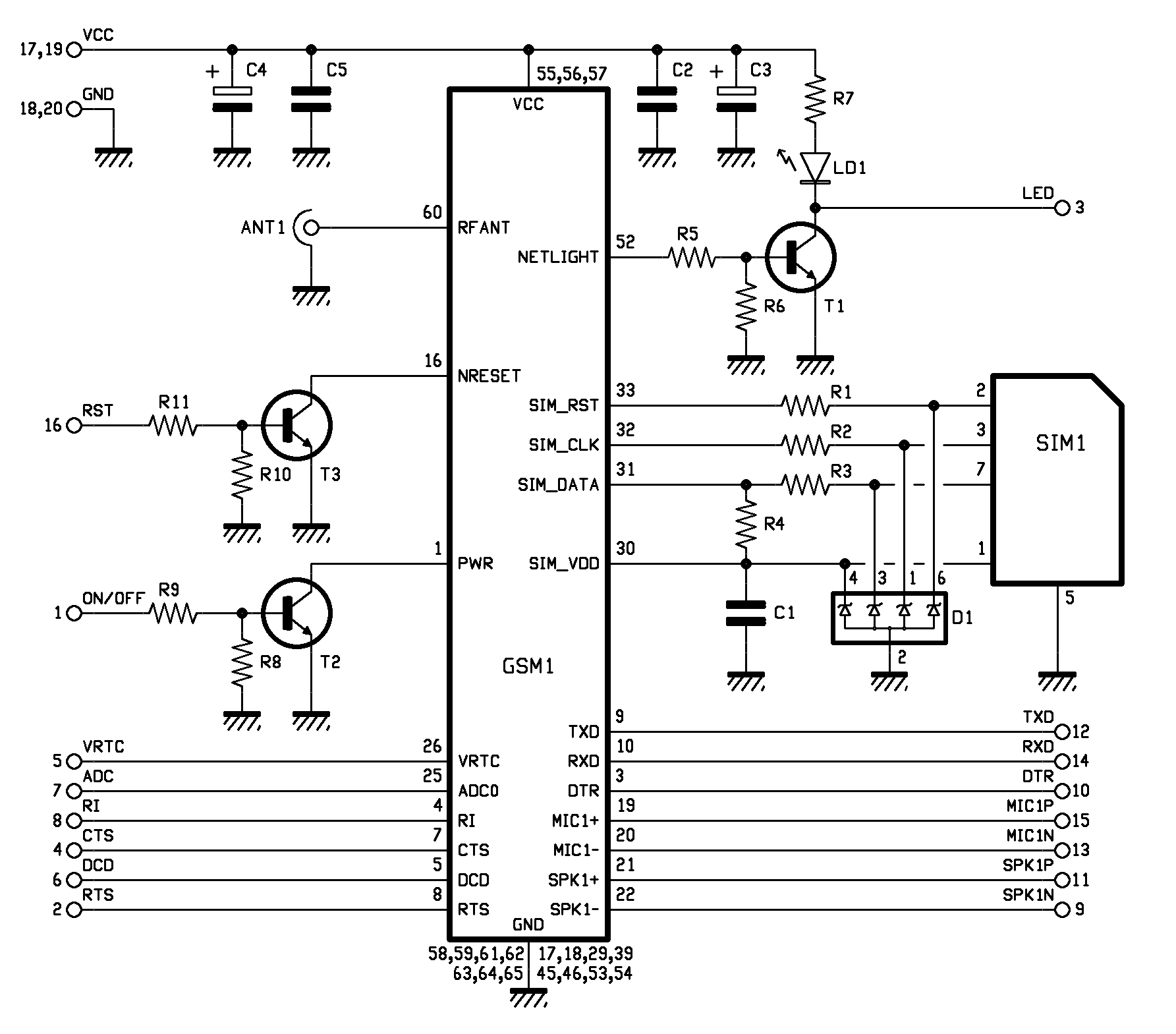
The printed circuit board features a 10-pin by 2-pin strip used for connection with the circuit board of the remote control device. Pin 1 (ON/OFF) is utilized by a microcontroller to control the power state of the GSM module....
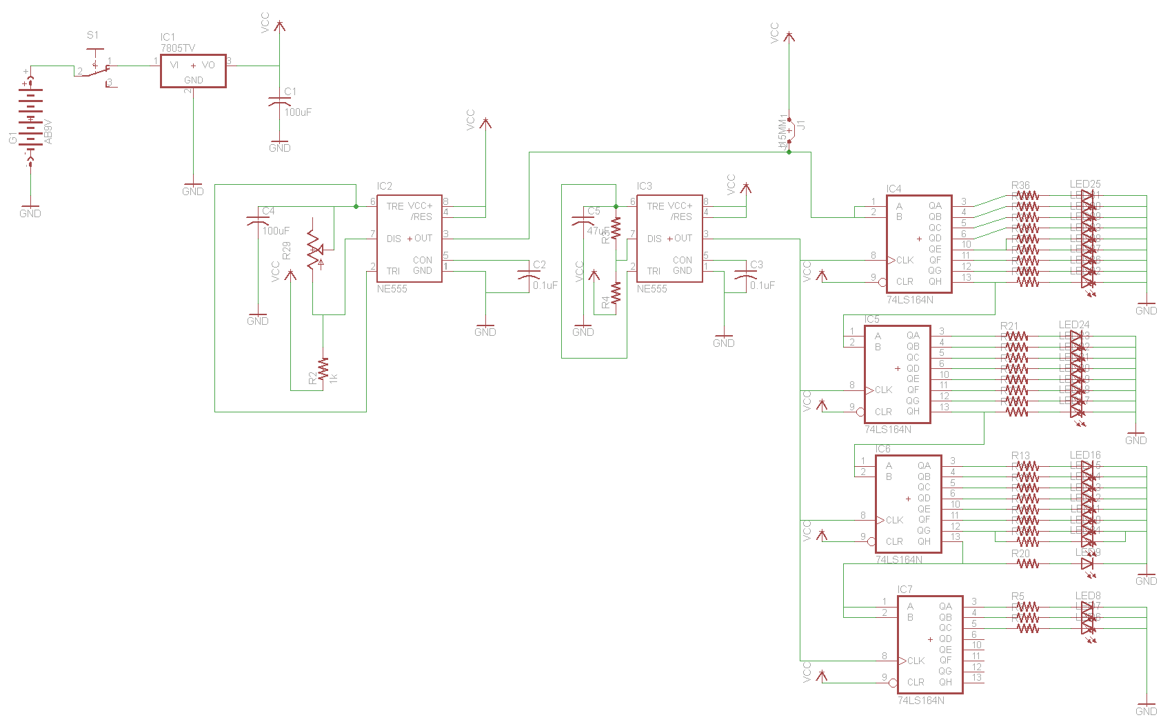
For the two-layer board schematic, six core integrated circuits (ICs) will be utilized: four 74LS164 shift registers and two 555 timers. The schematic will be constructed using the Eagle Layout Editor, as all required components are available in its...
How to control Christmas light displays with a computer. Controlling Christmas light displays using a computer involves creating a system that can manage multiple lighting circuits and sequences through software. This typically requires a combination of hardware and software components...
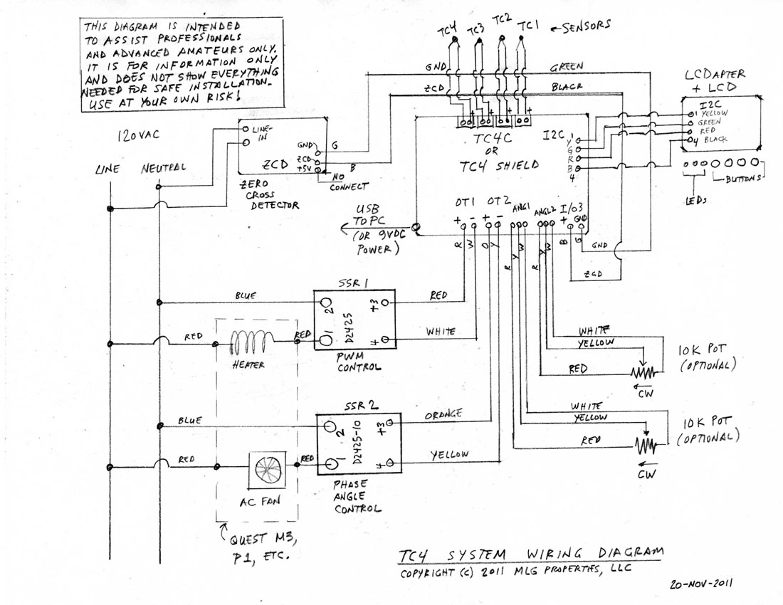
This is a complete standalone system compatible with Arduino Uno, which will be fully assembled, tested, and programmed prior to shipping. Users can select from various TC4 applications to be pre-programmed into the board. For those who wish to...
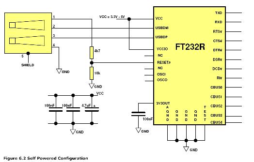
One issue this creates is that the USB port previously used for communication with HyperTerminal is no longer available. An alternative solution is required, which led to the selection of the FT232RL chip. This choice was made primarily due...