
oscillator and frequency divider schematics
A phase shift oscillator configuration can be utilized to generate sine waves, which can then be converted into square waves via an inverter. This method, while effective, may not be optimal for precision applications. The Schmitt trigger oscillator offers a more robust solution, particularly when built with discrete components. The feedback resistor in this configuration directly influences the frequency of oscillation, allowing for a straightforward method to vary the frequency through an additional control voltage applied via a resistor.
The core of the Schmitt trigger oscillator consists of a resistor-capacitor (RC) network, where the capacitor is connected from the input to ground, and the output is fed back into the input through a resistor. The output of this oscillator is a square wave, which can be adjusted for frequency by varying the resistor values. Integrated circuits like the 4093 or 40106 can be employed to create multiple oscillators, facilitating complex signal generation for applications such as musical synthesis.
In designing a frequency divider, the use of D flip-flops is common; however, alternative configurations utilizing bistable multivibrators can provide effective frequency division. The sequential switching bistable multivibrator circuit is particularly noted for its ability to halve the frequency of input signals. Careful consideration of component values, particularly resistors like R3, is crucial to ensure optimal performance. A typical design might aim for a current draw of 1-10 mA, with resistance values calculated based on the desired voltage supply.
When constructing these circuits, attention must be paid to duty cycle considerations, especially when generating square waves. A common approach to achieving a 50% duty cycle involves running the oscillator at double the target frequency and utilizing the output from the first frequency divider stage. This ensures that the output maintains the desired duty cycle, which is vital for applications requiring harmonic precision.
In summary, the combination of Schmitt trigger oscillators and frequency dividers can facilitate the creation of complex waveforms and signal processing tasks, particularly in sound synthesis applications. The careful selection of discrete components and circuit configurations is essential for achieving the desired performance characteristics.The other thing I thought of is using a phase shift oscillator followed by an inverter to turn the sine into a square wave, but it semms a rather crude solution. I`m also looking for the schematics to a frequencydivider. I know you can use a flip flop to halve the frequency, but I have only seen D flip flop used this way.
Is there a simple circuit that can easily be built with tiscrete components to do tha same thing I think a Schmitt trigger oscillator built with discrete components would work. The feedback resistor would set the frequency. You could even probably use a control voltage through another resistor to vary it. The simplest oscillator that I know is a Schmitt trigger with a capacitor from input to ground and a resistor from output to input. The output will be square wave. A 4093 will give four oscillators and a 40106, six. An astable multivibrator is a simple discrete solution. Use a 2 gang pot to adjust two resistances at once (it`s much harder to adjust 2 capacitances - especially of the size used in this sort of circuit) Using dividers means that the octave frequencies are locked to each other.
You may get a more interesting note if you use a free phase organ with non locked harmonics. This would entail 60 oscillators for a 60 note keyboard. As duke37 already suggested, you can use a CD4024 to generate seven lower octaves from each oscillator. (I`m assuming you will have twelve oscillators, one for each note, so you will need twelve CD4024s. ) If you really mean discrete, i. e. no ICs, look at the schematic for the transistorised clock on kabtronics. com. It uses two-transistor flip-flop circuits to divide frequencies by 2. As you can see, though, it takes a lot of space! Here is the heart of the Livingston Monarch. It uses pnp germanium alloy junction transistors and runs on -12V. Now, you should use npn transistors run on less than 6V, because of the limited base/emitter voltage.
And this is the frequency divider: (near the bottom, the squential switching bistable multivibrator) In the oscillator, the value of R3 depends on the current drawn by the load, which in this case is a chain of frequency dividers. Do you think this value is critical, as long as its not too high If it is, how can I calculate the current drawn The value of R3 isn`t critical.
I would choose a value that gives a current of around 1~10 mA, unless there`s some reason not to. So if your power supply is 9V, a value between about 1k and 10k will be fine. For example, 3k3. That oscillator will not produce a square wave with a duty cycle of exactly 50%. You probably want a 50% duty cycle to ensure the right mixture of harmonics. You can solve that problem by running the oscillator at twice the highest frequency you want, and taking your first output from the output of the first frequency divider. (The output from a frequency divider will always have a 50% duty cycle. ) For the frequency divider, I`m assuming you intend to use the "sequential switching bistable multivibrator" circuit.
This should work fine, but there are quite a few components in it, which is significant if you plan to build lots of them. Did you check out the kabtronics design It`s similar, but it might be a bit simpler. The reason why the transistor Schmitt oscillator`s output won`t be 50% is that the switching thresholds are not exactly the same distance away from the supply rails.
So the capacitor will take longer to charge to one threshold than it takes to discharge to the other threshold. It`s actually quite difficult to generate a square wave with a duty cycle of exactly 50%. The best way to do it is using a divide-by-two stage, as I suggested. If the duty cycle is not exactly 50%, the frequency spectrum will include unrelated frequencies as well as the fundamental and its ha
🔗 External reference
Related Circuits
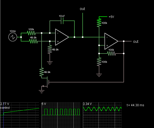
This circuit is a voltage-controlled oscillator, which is an oscillator whose frequency is determined by a control voltage. A 10 Hz sawtooth oscillator provides the control voltage in this case; this causes the frequency to rise slowly until it...
Here is a simple triangle/squarewave generator using a common 1458 dual op-amp that can be used from very low frequencies to about 10 Khz. The time interval for one half cycle is about R*C and the outputs will supply...
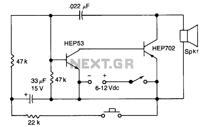
Closing the pushbutton switch initiates the siren, which then increases to a higher frequency. Releasing the switch causes the tone to decrease until switch S2 is closed again. The quality of the tone can be modified by altering the...

An individual sought to utilize a soldering iron to construct a frequency counter, a device that was previously absent in their lab. The schematic for the frequency counter was created using OrCAD PSpice, but the design files have since...
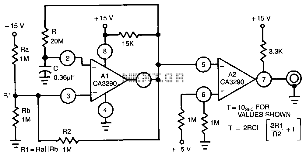
This circuit utilizes one half of the CA3290 BiMOS dual voltage comparator as a conventional multivibrator. The second half ensures frequency stability against the effects of output loading. Large values of the timing resistor, Rl, guarantee long time delays...
The transformer OCL and capacitor C1 create a tank circuit, which is coupled with sufficient turns to drive the grid in the lower left-hand winding. The output circuit is connected through a separate winding. For optimal waveform characteristics in...