
Yelp oscillator
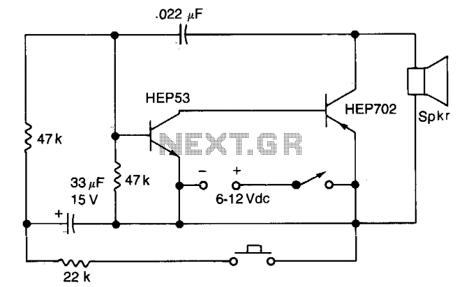
This circuit operates based on a pushbutton switch mechanism, which serves as the primary control for the siren's functionality. When the pushbutton switch is closed, it activates the siren circuit, causing the siren to produce a sound that rises in frequency. This frequency modulation is a key feature, allowing for a dynamic auditory signal that can be utilized in various applications such as alarms or alerts.
Upon releasing the pushbutton switch, the circuit enters a decay phase where the tone frequency gradually decreases. This fading effect can create a more natural sound transition, enhancing the auditory experience. The operation of the circuit is further influenced by switch S2, which, when closed, re-engages the higher frequency tone, allowing for continuous operation without the need to hold the pushbutton switch.
The tone quality, an essential aspect of the siren's performance, can be finely tuned through the adjustment of the 0.022 µF capacitor. This capacitor plays a crucial role in determining the frequency response of the circuit. By changing its value, the resonant frequency can be shifted, thereby altering the sound characteristics produced by the siren. This feature allows for customization of the audio output to meet specific requirements or preferences.
In summary, the described circuit provides a versatile and adjustable siren system, with controls that facilitate both the initiation of sound and the modulation of its frequency and quality. The integration of pushbutton and toggle switches, along with the variable capacitor, forms a user-friendly interface for effective sound management.Close the pushbutton switch and the circuit starts the siren up-shifting to a higher frequency. Release it and the tone slides down until S2 is closed again. Tone quality is adjusted by changing the 0.022 µf capacitor. 🔗 External reference
Related Circuits
Here is a simple triangle/squarewave generator using a common 1458 dual op-amp that can be used from very low frequencies to about 10 Khz. The time interval for one half cycle is about R*C and the outputs will supply...
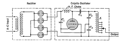
High frequencies are defined as those above 50,000 cycles per second. For industrial power supplies, the Golpitts circuit or the coupled-grid self-excited oscillator circuit is most commonly used. In either circuit, the alternating supply voltage is stepped up through...
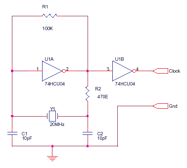
The 74HCU04 is a chip designed for specific circuit applications, while the HCT variant may not be suitable for such configurations. Capacitors C1 and C2 can be utilized up to 33pF, and resistor R2 can be adjusted to achieve...
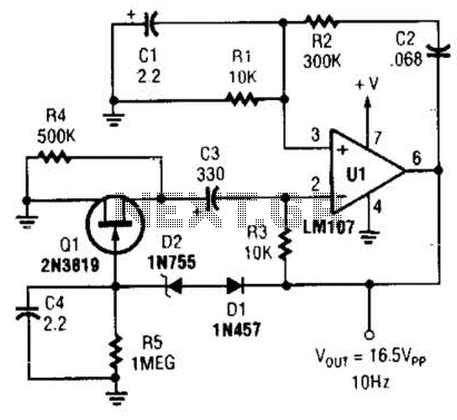
This Wien-bridge sine-wave oscillator utilizes a 2N3819 as an amplitude stabilizer. The 2N3819 functions as a variable-resistance element within the Wien bridge. The Wien-bridge oscillator is a type of electronic oscillator that generates sine waves. It employs a bridge circuit...
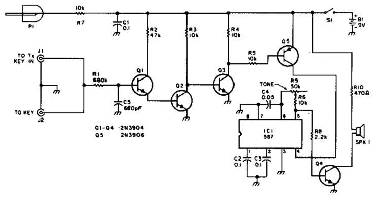
For use with low-power transmitters that require a positive keying voltage. The transistors Q1, Q2, and Q3 are configured as a switching amplifier. When the key is pressed, the collector of Q3 is pulled to ground, which activates Q5...
A phase-locked loop (PLL) is widely utilized in telecommunications, control systems, and various other electronic applications. PLLs can be employed to demodulate frequency-modulated (FM) signals and generate a stable output frequency. A phase-locked loop is an essential feedback control system...