
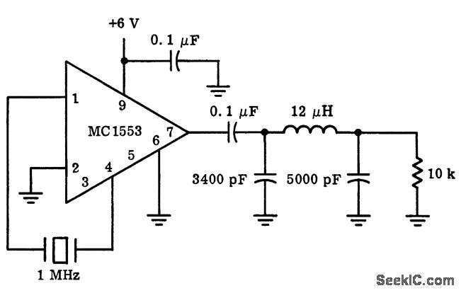
Oscillator
The tone generator circuit, designed around the Sallen-Key configuration, operates efficiently at low voltages, making it suitable for portable applications. The Sallen-Key low-pass filter configuration provides a unique advantage in maintaining oscillation stability, as it inherently supports sustained oscillation without the need for additional components typically required in Wien Bridge circuits. This design allows for a straightforward implementation of a tone generator that can be easily adjusted for frequency tuning while minimizing harmonic distortion through its filtering characteristics.
In practical applications, the circuit can be implemented using standard components, ensuring accessibility for hobbyists and professionals alike. The use of the LM10 op-amp is particularly advantageous due to its wide supply voltage range and rail-to-rail output capability, making it versatile for various audio applications. The design's ability to maintain a constant gain and output level is critical for testing balanced microphone inputs, as it ensures reliable performance across different operational conditions.
Overall, this tone generator design is a robust solution for generating audio signals at low voltages, providing a valuable tool for audio engineers and technicians in both testing and practical audio applications.A tone generator that runs on as little as 1. 5 Vdc, using the Sallen-Key configuration. And finally, I`ll apply the tone generator to implement a phantom powered signal source for testing balanced microphone inputs. Textbooks and web pages usually show the Wien Bridge configuration when describing single-opamp audio oscillators.
The Wien Bridge circuit shown in sketch form below will oscillate at a frequency equal to 1/(2 Oscillation will be self-starting when overall gain is greater than 3, so we want (R3/R4 + 1) > 3, or R3/R4 > 2. Once oscillation begins, additional circuit elements must be brought into play to maintain a constant output level with low harmonic distortion.
Tuning this kind of oscillator is complicated by the fact that the amount of gain required to maintain stable oscillation depends on how closely the tuning resistors and capacitors are matched. This is why the output level of an RC (resistance-capacitance) oscillator bounces around so much when setting the frequency.
If you need a tunable single-opamp RC oscillator, then you need to take special care to be sure that R`s and C`s remain equal as they are varied. Here I`ll diverge from standard practice and introduce a new circuit for RC oscillators. Based on the Sallen-Key equal-component-value second-order LP (low-pass) filter, my new circuit is nothing more than an LP filter with the input grounded.
Because it is second-order, this circuit has the capacity for sustained oscillation built in, which designers normally try to avoid. Frequency is the same as for the Wien Bridge oscillator, which is 1/(2 RC) where R = R1 = R2, and C = C1 = C2.
The condition for oscillation is also the same as for the Wien Bridge configuration, which is an overall gain greater than 3. Actually, most operating parameters of this new circuit are similar to the Wien Bridge oscillator. We`ll need to add a circuit which starts up with gain slightly greater than 3, and then maintains gain at exactly 3 once the sine wave output reaches the desired level.
My idea in thinking of the Sallen-Key architecture was that since it is already an LP filter, it should naturally suppress distortion in the form of harmonics, which are by definition above the fundamental. The LP filter and the oscillator are each tuned by the same two resistors and two capacitors, so that whenever you change the oscillation frequency, you have already tuned the LP filter at the same time.
Near the oscillation frequency, both BP (band-pass) and LP filters exhibit high `Q` and steep skirts. Far from the oscillation frequency however, their responses are quite different. The BP filter ultimately falls off at 6 dB/8va while the LP filter falls off at 12 dB/8va on the high side, potentially offering much better suppression of higher harmonics.
If I get a chance to study this effect in detail I`ll report my results here. I had in mind to design a tone generator which could operate on just two `N` cells in series, a total of +3. 0 Vdc. But running to end-of-life for the batteries would mean operating on as little as +1. 5 Vdc. So I started with Bob Widlar`s LM10 opamp and voltage reference which comes in an 8-pin DIP package from National Semiconductor and is available from distributors like Digikey.
This IC (integrated circuit) features a rail-to-rail main output, a common mode input range that includes ground, and it can be connected to single-polarity power supplies ranging from +1. 2 Vdc up to +40 Vdc. I chose an output level of -10 dBu for this circuit, or 245 mVac. This is a standard level used in home hi-fi and amateur recording equipment, and can be connected directly to any RCA input jack.
Output swing for this level is 0. 7 Vpp, which is well within reach for the LM10, even when powered at the minimum supply volt 🔗 External reference
Related Circuits
More: The provided input lacks specific details or context regarding an electronic circuit or schematic. To create a comprehensive electronic schematic description, it is essential to include key components, their interconnections, and the overall functionality of the...
The single-junction transistor is commonly utilized in sawtooth and pulse generators, and it can also be configured to create a basic sine wave generation circuit. As an oscillator circuit composed of discrete components, it requires a minimal number of...
A simple square wave oscillator can be created using two gates from a CMOS 4011 NAND chip. Alternatively, a CMOS 4001 chip or a TTL equivalent can also be utilized. In this circuit, the mark-space ratio can be independently...
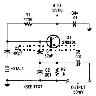
This is a simple Colpitts crystal oscillator for 1 to 20 MHz, which can be easily constructed from spare parts, provided that a crystal is available. The Colpitts oscillator is a type of electronic oscillator that utilizes a combination of...
I am attempting to construct a Hartley oscillator using a bypassed common emitter configuration. The goal is to achieve oscillation at a frequency of 200 kHz with a peak-to-peak voltage of 2 V, utilizing a BC547B transistor. The Hartley oscillator...
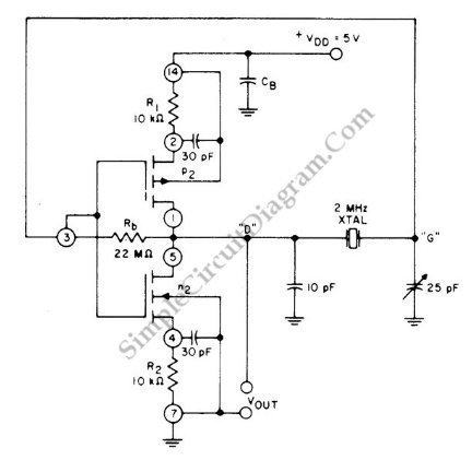
This circuit is a 2 MHz crystal oscillator utilizing a CMOS transistor pair. It is particularly suitable for applications in digital watches and clocks due to its low power consumption. The oscillator is constructed by connecting a CMOS transistor...
Warning: include(partials/cookie-banner.php): Failed to open stream: Permission denied in /var/www/html/nextgr/view-circuit.php on line 713
Warning: include(): Failed opening 'partials/cookie-banner.php' for inclusion (include_path='.:/usr/share/php') in /var/www/html/nextgr/view-circuit.php on line 713