
Hartley Oscillator

The Hartley oscillator is a type of LC oscillator that generates sinusoidal waveforms. It typically consists of an amplifier stage, which in this case is the bypassed common emitter configuration, and a feedback network formed by two inductors and a capacitor. The frequency of oscillation is determined by the values of these reactive components.
In this setup, the BC547B transistor serves as the active device. The common emitter configuration provides the necessary gain and phase shift for oscillation. The bypass capacitor is used to enhance the AC performance of the transistor by providing a low impedance path for the AC signals while maintaining DC biasing.
To achieve a frequency of 200 kHz, the values of the inductors (L1 and L2) and the capacitor (C) must be carefully selected. The frequency of oscillation (f) in a Hartley oscillator can be approximated using the formula:
f = 1 / (2π√(L_total * C))
where L_total is the total inductance, which is the sum of the two inductors in series. For a target frequency of 200 kHz, suitable values for L and C must be calculated, ensuring that the peak-to-peak output voltage reaches the desired 2 V.
The circuit should also include biasing resistors to set the operating point of the transistor, ensuring it remains in the active region during oscillation. Additionally, a coupling capacitor may be employed at the output to block any DC component, allowing only the AC oscillation to be observed.
It is essential to simulate the circuit using electronic design automation software to verify the performance before physically constructing the oscillator. This simulation can help identify any potential issues with component values or stability, enabling adjustments to be made to achieve the desired oscillation characteristics.hi Im trying to construct a Hartley Oscillator. I am using a bypassed common emiter and i am trying to get a 200kHz 2Vp-p oscilation. With a BC547B.. 🔗 External reference
Related Circuits
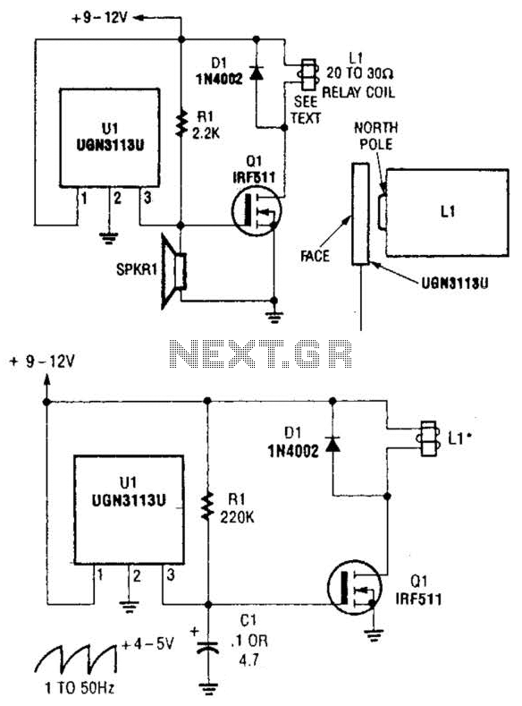
Although not intended for this application, a Hall-effect switch can be utilized as the foundation for an unconventional oscillator. The oscillator can be reconfigured, as illustrated in Fig. B, to enable the circuit's oscillating frequency to be regulated through...
As shown in the figure, the 555 timer, resistors R1, RP1, and capacitor C1 form a controlled audio oscillator. The frequency of the oscillator is given by the formula f = 1.44 / ((R1 + 2 * RP1) *...
The signal can be received using a standard FM radio receiver. It should be coupled by a disc capacitor of approximately 0.1 µF to the main stage. To implement a circuit capable of receiving the specified FM signal, a standard...
The SI2171 is a sub-package of the SI2170. For further details, please refer to the SI2170 description. The datasheet for the SI2171 can be downloaded from the link provided below. By Silicon Laboratories. The SI2171 is a versatile integrated circuit...
The Colpitts oscillator has been redrawn for clarity. The inductor (L) is approximately 1.5 µH with 19 turns wound on a T50-6 core (yellow). The capacitor (C6) value has been determined experimentally, with a combination of 69 pF (using...
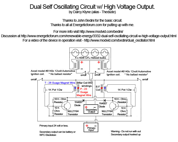
A Tesla pancake coil is connected in series with a bifilar wound coil to generate resonance and a sharp gradient discharge, which creates a vacuum flux. The circuit operates with a CFL at approximately 0.07 amps and 12.42 volts,...