
Oscillator circuits

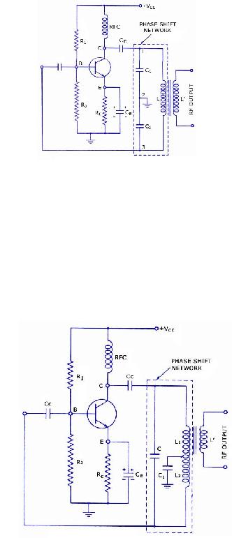
The phase shift oscillator operates by utilizing a combination of resistive feedback and RC phase shifting to achieve sustained oscillations. The negative feedback from the collector, due to the inherent phase inversion of the transistor, is countered by the positive feedback provided by the three RC networks. Each RC network contributes a precise phase shift, enabling the total phase shift to reach 360 degrees, which is essential for oscillation.
The inclusion of a Varactor diode introduces a nonlinearity that is critical for harmonic generation. As the input sine wave is applied, the Varactor's capacitance varies with the frequency, leading to the generation of harmonics. The design incorporates a fundamental filter that selectively allows the fundamental frequency to pass while effectively blocking unwanted harmonics, ensuring that the output maintains a clean sine wave signal.
The choke in the circuit serves a dual purpose: it provides a path for the DC bias while simultaneously isolating the circuit from unwanted RF interference. This is particularly important in maintaining the integrity of the oscillator's operation and preventing potential disruptions from external RF sources.
The capacitor positioned at the bottom of the inductor is chosen for its large capacitance and low reactance characteristics. This component is essential for blocking DC while allowing RF signals to ground the inductor, which is necessary for the proper functioning of the resonant network.
The parallel resonant network formed by the Varactor diode and the inductor is finely tuned to resonate at the desired harmonic frequency. The fixed reverse bias applied to the Varactor ensures stable operation and consistent performance in generating microwave frequencies. The overall design, while represented as a lumped circuit, is effectively a sophisticated arrangement of stripline or waveguide sections capable of achieving very high frequencies, making it suitable for advanced applications in microwave technology.The phase shift oscillator of Figure above produces a sinewave output in the audio frequency range. Resistive feedback from the collector would be negative feedback due to 180o phasing (base to collector phase inversion). However, the three 60o RC phase shifters ( R1C1, R2C2, and R3C3) provide an additional 180o for a total of 360o.
This in-phase feedback constitutes positive feedback. Oscillations result if transistor gain exceeds feedback network losses. A Varactor or variable capacitance diode with a nonlinear capacitance vs frequency characteristic distorts the applied sinewave f1 in Figure below, generating harmonics, f3. The fundamental filter passes f1, blocking the harmonics from returning to the generator. The choke passes DC, and blocks radio frequencies (RF) from entering the Vbias supply. The harmonic filter passes the desired harmonic, say the 3rd, to the output, f3. The capacitor at the bottom of the inductor is a large value, low reactance, to block DC but ground the inductor for RF.
The varicap diode in parallel with the indctor constitutes a parallel resonant network. It is tuned to the desired harmonic. Note that the reverse bias, Vbias, is fixed. The varicap multiplier is primarily used to generate microwave signals which cannot be directly produced by oscillators. The lumped circuit representation in Figure above is actually stripline or waveguide sections. Frequenies up to hundreds of gHz may be produced by varactor multipliers. 🔗 External reference
Related Circuits
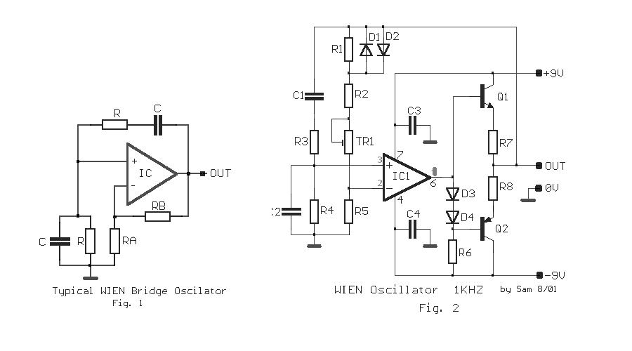
The circuit was designed to create an electronic oscillator known as the Wien Bridge Oscillator, which can be used for the generation of low-frequency sine waves. The Wien Bridge Oscillator is a type of electronic oscillator that generates sine waves....
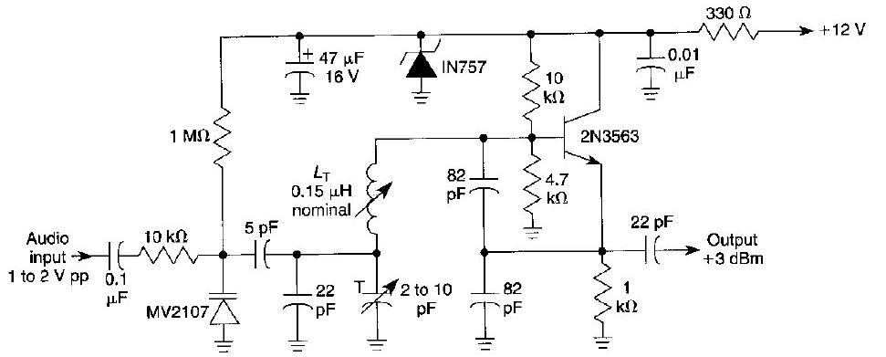
This FM oscillator can be utilized for wireless audio, microphone, and part-15 applications where a stable frequency-modulated oscillator is required. The FM oscillator is an essential component in various communication systems, particularly in wireless audio transmission and microphone applications. It...
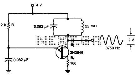
A tuned circuit can be incorporated into the current-pulse path of a UJT oscillator to generate a 3750-Hz sinusoidal signal at output B2, using the specified component values. The UJT (Unijunction Transistor) oscillator is a type of relaxation oscillator that...
This report provides details on the principles and operation of an amplifier known as the Wien Bridge Oscillator. The oscillator was designed as part of a laboratory exercise, which was not attended, thus this document will focus on the...
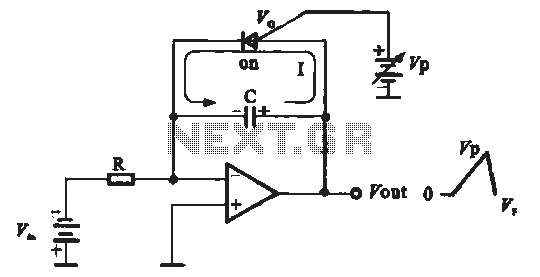
A sawtooth voltage-controlled oscillator operates by first generating a negative potential maximum at the output of the comparator. This output is then fed to the inverting input terminal through resistor R1, which is part of the relaxation oscillator. The...
This is a sine wave oscillator circuit, also known as an amplitude-stabilized sine-wave oscillator. It provides a high-purity sine wave output. This sine wave oscillator circuit is designed to generate a stable sine wave output with minimal distortion, making it...