
Wien Bridge Oscillator
The Wien Bridge Oscillator is a type of electronic oscillator that generates sine waves and is widely used in audio applications and signal processing. It utilizes a bridge circuit configuration that includes a combination of resistors and capacitors to establish the necessary conditions for oscillation. The key components of the Wien Bridge Oscillator include two resistors and two capacitors arranged in a specific manner to create a frequency-selective feedback network.
In operation, the oscillator employs positive and negative feedback to maintain oscillations. The positive feedback is achieved through the bridge configuration, while the negative feedback is typically provided by a variable resistor or a light bulb, which serves to stabilize the amplitude of the oscillation. This automatic gain control mechanism is crucial for preventing distortion and ensuring that the output signal remains within an acceptable range.
The frequency of oscillation can be calculated using the formula:
\[ f = \frac{1}{2\pi R_1 C_1} \]
where \( R_1 \) and \( C_1 \) are the values of the resistors and capacitors in the bridge circuit. By adjusting these components, the frequency can be tuned to the desired value.
The Wien Bridge Oscillator is notable for its simplicity and effectiveness, making it a popular choice for generating low-frequency sine waves. Its design principles also serve as a foundation for understanding more complex oscillator circuits, such as the Colpitts and Hartley oscillators, which utilize similar feedback mechanisms but incorporate different configurations of inductors and capacitors. Overall, the Wien Bridge Oscillator exemplifies fundamental concepts in electronic circuit design, particularly in the field of signal generation and processing.This report entails the details on the principles and operation of an amplifier known as the Wien Bridge Oscillator. This oscillator was designed as part of a laboratory exercise, which unfortunately I did not get to participate in, therefore, this write will contain more discussion and thoughts on the theoretical aspect behind this model and vari
ous other types of amplifier models. It is crucial that when constructing an oscillator circuit that it consists of the following two sections: forward gain and positive( feedback= 1G †0. For) the essential oscillation to occur the Barkhausen criteria must be satisfied. A diagram of a basic oscillator circuit can be seen in figure 1. Figure 1 - Diagram including the negative feedback factor courtesy of Lab 3: Design, Construction & Test of a Variable Frequency Sinusoidal Oscillator instruction sheet Barkhausen criteria states that: The magnitude of the loop gain must be 1, the phase shift of the loop gain must be 0G‚ ° or 180G‚ ° plus an integer multiple of 360G‚ °.
This criterion is necessary but not sufficient as it only deals with observation based upon a linear circuit. The conventional oscillator is created in order that its amplitude will be controlled when it starts oscillating.
In order that a linear circuit may oscillate, the Barkhausen criteria must be met. That is, its loop phase must be one and the phase around the loop must be an integer multiple of 360 degrees. The linear oscillator theory does not explain how the oscillator starts up or the method of determining the amplitude as the linear oscillator can sustain any amplitude.
The loop gain is initially larger than unity in practice. All circuits produce noise and a selected range of that noise will be close to the required frequency. The amplitude of the frequency rises exponentially each time around the loop when the loop gain is greater than one.
Therefore, the oscillator will start with a loop gain greater than one. It is required that the loop gain be slightly larger than one, however, in a practical sense it is often considerably greater than one. The system will oscillate sooner with a larger loop gain. Greater loop gains also recompense for gain disparities with temperatures and the desired frequencies of a tuneable oscillator.
In order for the oscillator to switch on, the loop gain must be larger than one under all feasible conditions. In a theoretical sense, the oscillator amplitude will increase without limit, therefore a loop gain greater than one does have its disadvantages.
In practice, the amplitude will rise until the output runs into some restraining factor such as the power supply voltage; that is the amplifier output runs into the supply rails or the amplifier output current limits. The effective gain of the amplifier is decreases as a result of the limited output current. The limiting action produces a steady output voltage and has two substantial effects; harmonic distortion is produced and the stability of the oscillator is affected.
The amount of distortion is associated to the additional loop gain employed for start up. Should there be extra loop gain at small amplitudes; the gain must decrease further at higher instantaneous amplitudes. This effectively produces more distortion. The quantity of distortion is also connected with the final amplitude of the oscillation. Although an amplifier`s gain is ideally linear, in practice it is nonlinear. The nonlinear transcribing function can be viewed as a Taylor series. For small amplitudes, the higher order terms have little effect. For larger amplitudes, the nonlinearity is pronounced. Consequently, for low distortion, the oscillator`s output amplitude should be a small fraction of the amplifier`s dynamic range.
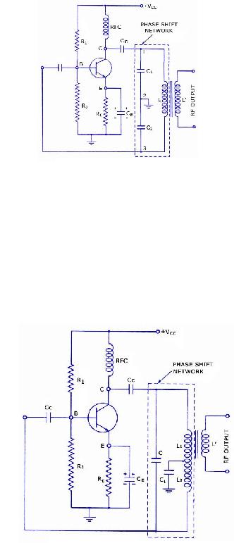
combines Inductance (L) with Capacitance (C) for frequency determination. The Colpitts oscillator is also therefore known as the LC oscillator. The most predominant feature from th 🔗 External reference
Related Circuits
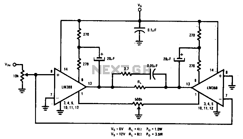
This circuit is designed for low voltage applications that demand high power outputs. Typical output power levels are low into 4 ohms from 6 V and 3 V into 8 ohms from 12 V. Coupling capacitors are not required...
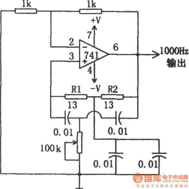
The circuit illustrated in the diagram is a 1 kHz sine wave oscillator circuit. Based on a double-T circuit configuration, it utilizes a standard 741 operational amplifier to generate a 1000 Hz sine wave output. The circuit begins oscillation...

This circuit is a voltage-controlled oscillator (VCO) that utilizes the 555 timer integrated circuit (IC) as its primary component. The 555 timer is configured as an astable multivibrator, enabling it to function as an oscillator. An astable multivibrator is...
This mini metronome provides a linearly scaled output with a range of 40 to 208 beats per minute. The transistors Q1 and Q2 facilitate the linear frequency variation of IC1. The described mini metronome circuit utilizes an integrated circuit (IC1)...
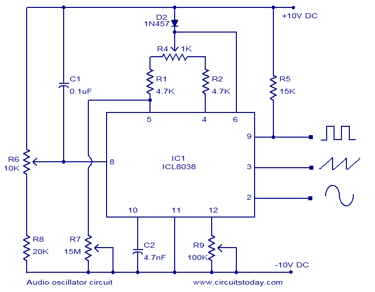
ICL8038-based audio oscillator circuit. Simultaneous sine, triangle, and square waveforms. Dual supply operation. Covers the full audio frequency range. The ICL8038 is a precision waveform generator integrated circuit that can produce sine, triangle, and square waveforms simultaneously. This versatility makes...
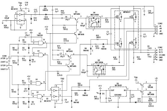
The following circuit illustrates an N-Channel H-bridge motor drive circuit diagram. Features include low voltage motor drives utilizing N-channel MOSFETs. The N-Channel H-bridge motor drive circuit is designed to control the direction and speed of a DC motor using low...