
Oscillator configuration in transmitter

The oscillator circuit for an AM transmitter typically serves as the primary signal generator, producing a carrier wave that is modulated with audio information. This circuit often employs a combination of active and passive components, including transistors, capacitors, resistors, and inductors, to create oscillation at the desired frequency.
In a basic design, the oscillator may utilize a transistor in a common-emitter configuration. The input signal is fed into the base of the transistor, where it is amplified. Feedback is provided through a network of resistors and capacitors, which determines the oscillation frequency. The output is then coupled to an LC (inductor-capacitor) tank circuit that helps to filter and stabilize the oscillation, ensuring a clean carrier wave.
For AM transmission, the modulated signal is generated by varying the amplitude of the carrier wave in accordance with the audio input. This modulation can be achieved using a simple variable resistor in series with the audio signal, allowing the amplitude of the carrier wave to change as the audio signal varies.
Careful consideration must be given to component values to ensure the oscillator operates within the desired frequency range and maintains stability under varying conditions. Additionally, the design may include tuning elements to allow for frequency adjustments, which is essential for compliance with broadcasting regulations and for optimizing transmission quality.
Overall, the oscillator circuit is a fundamental component of AM transmitters, playing a crucial role in the generation and modulation of radio frequency signals.Hi Expert, I recently receive some question on an oscillator in some AM transmitter. I searched the web and find this circuit. According to author,.. 🔗 External reference
Related Circuits
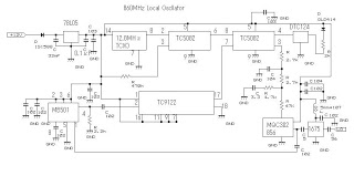
This 860 MHz Phase Locked Loop (PLL) oscillator circuit is designed for a 1200 MHz transverter's local oscillator with 435 MHz rigs. The oscillator circuit utilizes Toshiba PLL synthesizer ICs. The TC9122P is a user-friendly preset counter for determining...
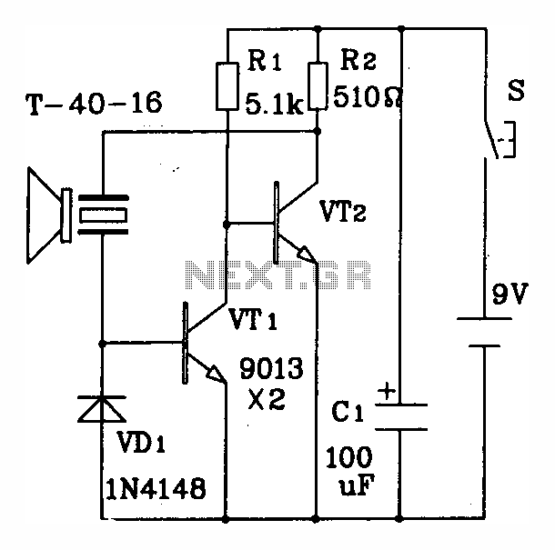
The discrete components ultrasonic transmitting circuit T/R-40-16 is capable of emitting a series of ultrasonic signals at a frequency of 40 kHz. This circuit operates at a voltage of 9V, with an operating current of 25 mA, and can...
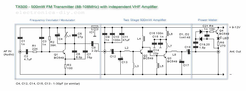
The TX500 is an easy-to-build 500mW FM transmitter. It consists of three main components: a modulator/oscillator, a two-stage 500mW VHF amplifier, and an LED-based power meter. The TX500 enables the transmission of audio signals to the FM band at...
This oscillator is typical for operation between 350 to 500 MHz. The microstrip inductor is implemented as a printed circuit board (PCB) trace. The output power ranges from 55 to 100 mW into a 50-ohm load, with frequency stability...
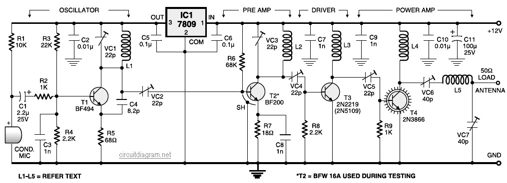
A four-stage FM transmitter circuit diagram utilizes four radio frequency stages: a VHF oscillator designed around the BF494 transistor (T1), a preamplifier based on the BF200 transistor (T2), a driver built with the 2N2219 transistor (T3), and a power...
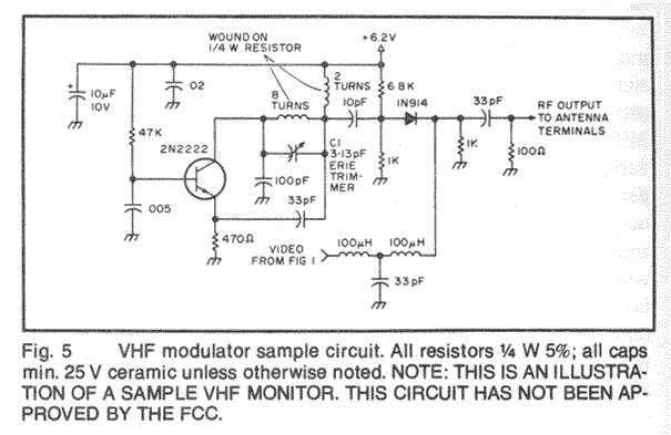
In this fast-paced world, there is little time for inconveniences and a greater need for portability and adaptability. The idea for an Audio/Video transmitter stems from this need. There may have been times when you’ve wanted to hook up...