
4 Stage FM transmitter circuit diagram
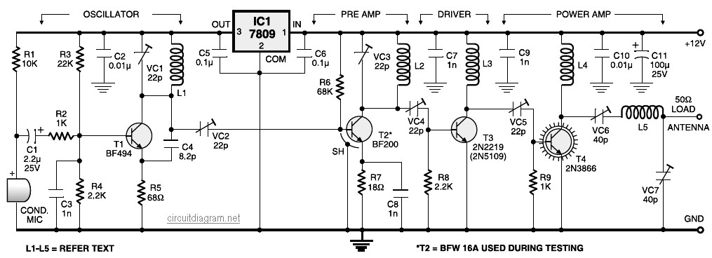
This FM transmitter circuit is structured to include a VHF oscillator that generates the carrier frequency, which is modulated by audio signals from the condenser microphone. The BF494 transistor serves as the oscillator, providing the necessary frequency stability and performance. The preamplifier stage, utilizing the BF200 transistor, amplifies the audio signals from the microphone to ensure that the modulation is effective. The driver stage, constructed with the 2N2219 transistor, further amplifies the RF signal before it reaches the power amplifier stage. The power amplifier, built around the 2N3866 transistor, is responsible for boosting the output signal to a level suitable for transmission over longer distances.
The circuit's performance can be influenced by various factors, including the quality of the components used, the layout of the circuit, and the operating environment. Proper tuning of the circuit is essential to achieve optimal transmission range and audio quality. The use of a trimpot (P1) allows for fine adjustments to the circuit, enabling the user to optimize the oscillator frequency and ensure stable operation.
The overall design of this FM transmitter circuit is suitable for applications requiring short-range audio transmission, such as personal broadcasting or educational demonstrations. The inclusion of a variable frequency oscillator allows for flexibility in tuning to different frequencies within the FM band, making it a versatile choice for various communication needs.4 Stage FM transmitter circuit diagram. It uses four radio frequency stages: a VHF oscillator built around transistor BF494 (T1), a preamplifier built around transistor BF200 (T2), a driver built around transistor 2N2219 (T3) and a power amplifier built around transistor 2N3866 (T4). A condenser microphone is connected at the input of the oscillat or. This is the FM transmitter circuit which apply 4 radio frequency stages, that are a VHF oscillator designed around transistor BF494 (T1), a preamplifier designed around transistor BF200 (T2), a driver designed around transistor 2N2219 (T3) and also a power amplifier designed around transistor 2N3866 (T4). A condenser microphone is wired at the input of. This circuit is a powerful three stage, 9V FM transmitter (Tx) with a range of up to 1 kilometer in the open.
It uses an RF transistor in its output stage and two BC547`s for the first two stages. Distance of trans-mission is critically dependent on the operating Conditions (in a building or out on. The following diagram is the schematic diagram of 4 transistors FM transmitter circuit designed by Paul K.
Sherby. Components List: R1, R2, R8 = 1K R3 = 100K R4 = 150K R5, R7 = 10K R6 = 220 ohm R9 = 10 ohm P1 = 5K trimpot D1 = 1N4002 Q1, Q2 = 2N3904 Q3, Q4 = 7001, NTE123AP C1. Here the SW transmitter circuit based on IC BEL1895. This particular transmitter circuit works in shortwave HF band (6 MHz to 15 MHz), and can be applied for shortrange communication and for educational purposes.
The circuit is composed of a mic amplifier circuit, a variable frequency oscillator, and modulation amplifier stages. Transistor T1 (BF195) is. This circuit is a wireless car alarm system that is built using two circuit modules, namely modules of transmitter and receiver modules.
This circuit works on FM radio waves. Car alarms can be used on vehicles that have a 6-12VDC power supply. You can use the voltage stabilizer if your car power supply is too. This the Good Quality FM transmitter for your stereo or any other amplifier gives you a pretty good signal strength up to a range of 500 metres having a power output of about 200 mW. This circuit can be operated with a 9V battery. The audio-frequency modulation stage is constructed close to transistor BF494 (T1), . 🔗 External reference
Related Circuits
A varying brightness AC lamp circuit utilizes a silicon-controlled rectifier (SCR) to gradually adjust the intensity of a 120-volt light bulb by controlling the duration of AC line voltage applied to the lamp during each half cycle. The circuit...
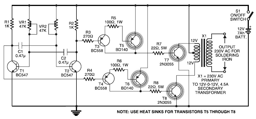
Simple Inverter for Soldering Iron. This is a straightforward and cost-effective inverter designed to operate small power soldering irons (25W, 35W, etc.) in the absence of mains supply. The circuit requires eight transistors along with several resistors and capacitors....

A gain stage is being constructed using Decware's Zkit4 to serve as a buffer in front of an LM3875 gain clone. The chip amplifier has sufficient... The gain stage circuit designed using Decware's Zkit4 is intended to provide impedance matching...

The thermostat electric circuit operates as depicted in the figure. It has three settings: off, low power (Lo), and high power (Peru HL). When the DIP switch SA is set to the Lo position, 220V AC is directed through...
You'll find that this is a very easy project to build. It will transmit good quality sound in the FM band (88 - 108 MHz). One important item is that the IC chip operates on 3 volts DC. The...
This infrared transmitter utilizes pulse width modulation (PWM). The transmitter is equipped with an LM567 tone decoder circuit. An audio signal (at least 50 mV peak-to-peak) is amplified with transistor T1 and subsequently used to modulate IC1. The frequency...