
Discrete circuit elements constituting the ultrasonic transmitter
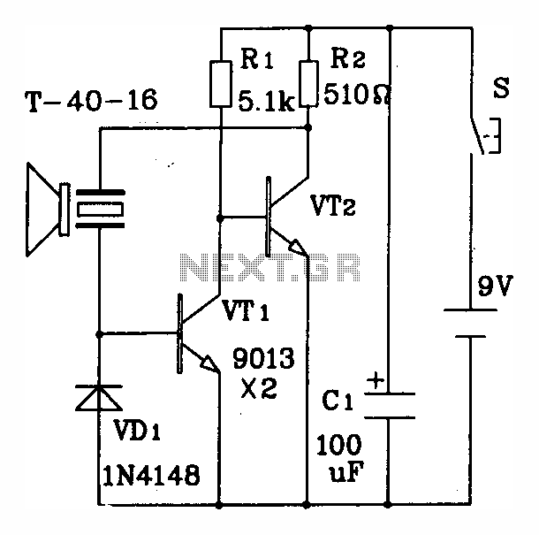
The T/R-40-16 ultrasonic transmitting circuit utilizes discrete components to generate high-frequency ultrasonic signals. The circuit is designed to operate efficiently at a supply voltage of 9 volts, drawing a current of 25 milliamperes during operation. The primary function of this circuit is to emit ultrasonic waves at a frequency of 40 kHz, which is commonly used in various applications such as distance measurement, object detection, and proximity sensing.
The circuit typically consists of a signal generator, which may include a 555 timer IC or a microcontroller, to produce the desired frequency output. The generated signal is then amplified using a suitable transistor or operational amplifier to ensure sufficient power for transmission. The output stage is connected to an ultrasonic transducer, which converts the electrical signal into ultrasonic sound waves.
The effective control distance of the circuit is up to 8 meters, making it suitable for applications where short-range ultrasonic communication or sensing is required. The design may also include additional components such as resistors, capacitors, and diodes to stabilize the circuit and filter out noise, ensuring a clean output signal.
In summary, the T/R-40-16 ultrasonic transmitting circuit is a compact and efficient solution for generating ultrasonic signals, with its straightforward design allowing for easy integration into various electronic systems.Discrete components ultrasonic transmitting circuit T / R-40-16 can emit a series of ultrasonic signal of 40kHz. This circuit voltage of 9V, operating current of 25mA, control distance of up to 8m.
Related Circuits
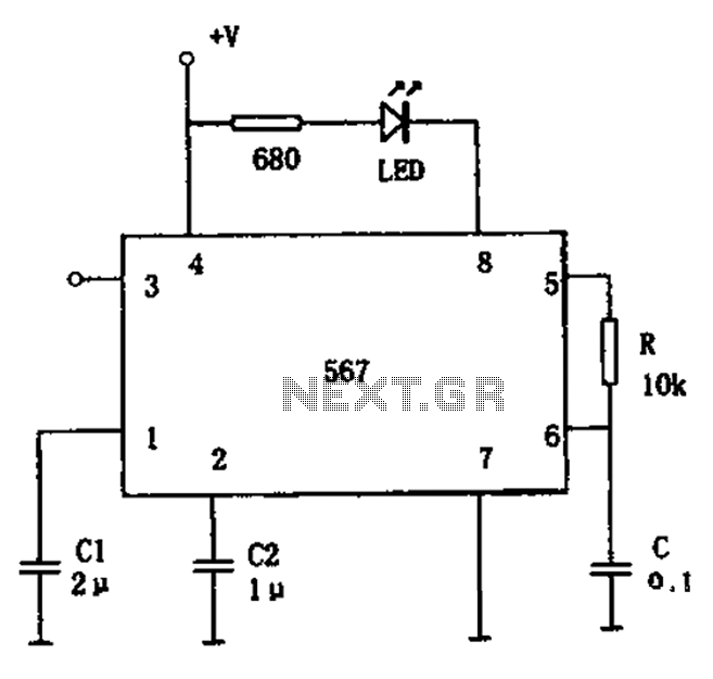
The FM demodulation circuit is illustrated in Figure 567. The FM signal is input at pin 3, and the demodulated signal is output from pin 5. The center frequency of the FM demodulation circuit is determined by the formula...
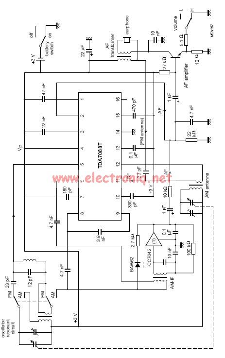
The TDA7088 features a frequency-locked-loop (FLL) system with an Intermediate Frequency (IF) of approximately 70 kHz. This circuit can be powered using a 3-volt battery cell or a regulated power supply. The TDA7088 is a highly integrated FM radio receiver...

This circuit represents a remote control unit that utilizes radio frequency signals to operate various electrical appliances. The remote control unit features four channels, which can be expanded to twelve. This circuit stands out from similar designs due to...

This is a circuit known as a Wien bridge oscillator circuit. The circuit features both positive and negative feedback loops and operates under the control of an operational amplifier (op-amp). The oscillation frequency is determined by the RC time...
The circuit operation begins by transmitting stereo surround sound signal quality information through the master volume circuit. This drives the left channel connected to the LCH Model TL072 IC1A and IC1B, which are linked to the right channel (Rch)....
This circuit is a difference amplifier. It functions as an inverting amplifier that enables the subtraction of two voltages, effectively performing a summation. The difference amplifier is a fundamental circuit configuration in analog electronics, primarily used for amplifying the difference...
Warning: include(partials/cookie-banner.php): Failed to open stream: Permission denied in /var/www/html/nextgr/view-circuit.php on line 713
Warning: include(): Failed opening 'partials/cookie-banner.php' for inclusion (include_path='.:/usr/share/php') in /var/www/html/nextgr/view-circuit.php on line 713