
OSCILLOSCOPE COUNTER PREAMPLIFIER
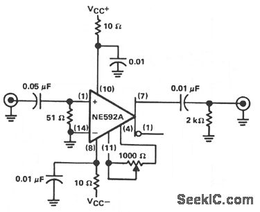
The described circuit functions as a high-frequency amplifier, designed to deliver a stable voltage gain while maintaining low noise levels across a specified bandwidth. The gain of 20 ±0.1 dB indicates a well-regulated amplification factor, suitable for applications requiring consistent signal enhancement.
The inclusion of a 0.05 µF capacitor in series with the input terminal is a critical design element, as it influences the low-frequency response of the amplifier. By increasing the capacitance, the circuit can extend its ability to process lower frequency signals, thereby enhancing overall performance in applications where low-frequency fidelity is essential.
The specified input noise level of approximately 10 µV is indicative of a high-quality amplifier, as it suggests minimal interference and signal distortion within the operating bandwidth of 15.7 MHz. This low noise characteristic is crucial for precision applications, such as instrumentation and communication systems, where signal integrity is paramount.
The calibration feature of the circuit is facilitated by a 1 kΩ potentiometer connected between specific pins, allowing for fine-tuning of the gain. This adjustability is essential for ensuring that the amplifier meets the required specifications for various applications, providing flexibility in different operational contexts. The ability to achieve a precise voltage gain of 10 while preserving the scale factor enhances the usability of the instrument, making it suitable for a wide range of electronic measurement tasks.
Overall, this circuit design reflects a careful balance between gain, frequency response, and noise performance, making it a versatile choice for high-frequency amplification needs in electronic systems.The circuit will provide a 20 ±0. 1 dB voltage gain from 500 kHz to 50 MHz. The low-frequency response of the amplifter can be extended by increasing the value of the 0. 05- F capacitor connected in series with the input terminal. This circuit will yield an input-noise level of approximately 10 V over a 1 5. 7-MHz bandwidth. The gain can be catib rated by adjusting the potentiometer connected between pins 4 and 11. The 1-K © potentiometer can be adjusted for an exact voltage gain of 10. This preserves the scale factor of the instrument. 🔗 External reference
Related Circuits

A general-purpose preamplifier/mixer accepts up to four inputs, has a gain of 1600, and provides bass and treble controls that can be varied ± 10 dB at 100 Hz and 10 kHz respectively. More: IC1 and IC2 = LM301A. This...
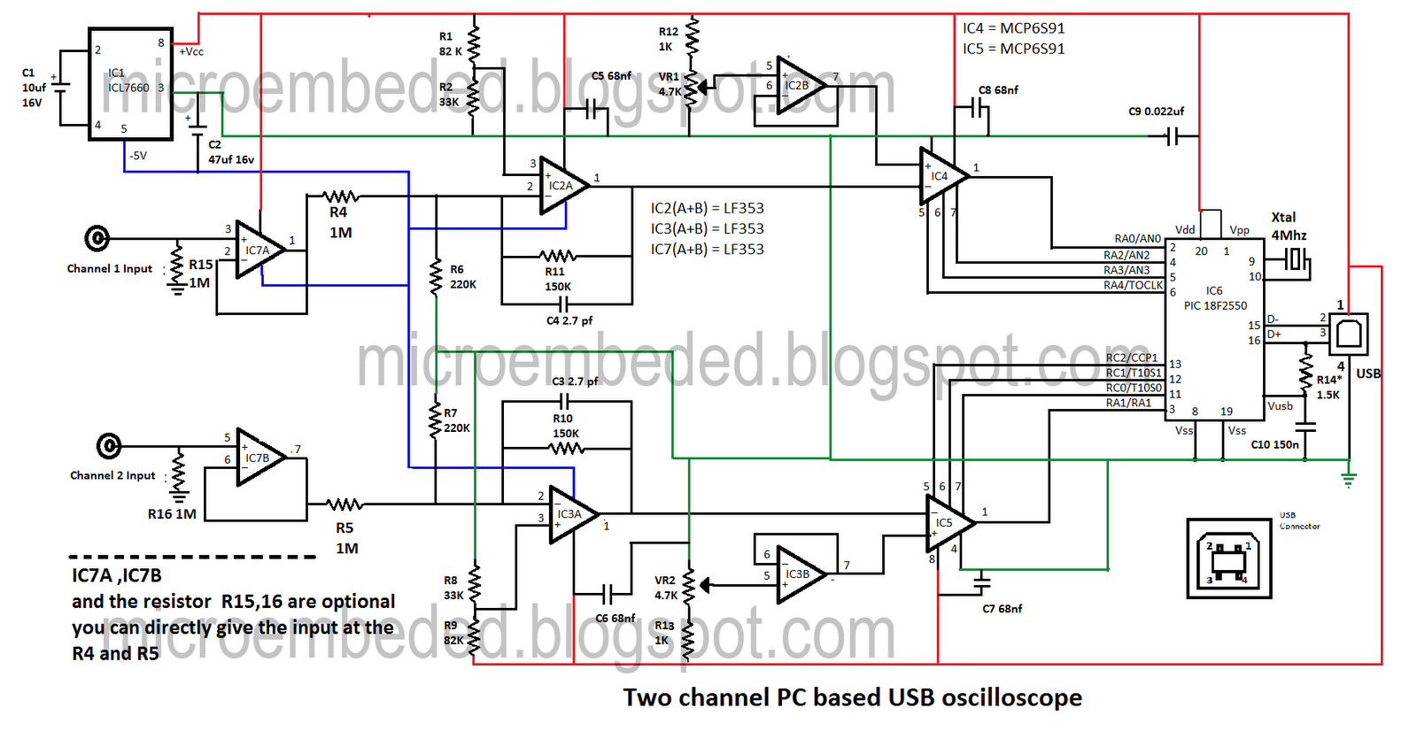
Portable PCs are now common, and a USB connection is a more effective solution. This document presents an oscilloscope that utilizes the USB port of a PC, operating at frequencies up to 10 kHz with an input voltage range...

The discrete-gate up/down-counter design has the unusual property of freezing, or saturating, when it reaches its lowest count in the down-count mode or its highest count in the count-up mode instead of rolling over and resetting as do most...
This design synthesis considers the accuracy of frequency measurement and the requirements for response time. For instance, when measuring a frequency of 1 Hz, the measurement duration must exceed 1,000 seconds to accurately count the gate width. To ensure...
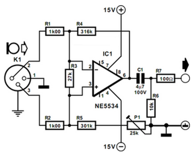
The preamplifier is designed for use with dynamic (moving coil MC) microphones with an impedance of up to 200 ohms and balanced terminals. It features a straightforward design and can be regarded as a single-stage instrument amplifier utilizing a...
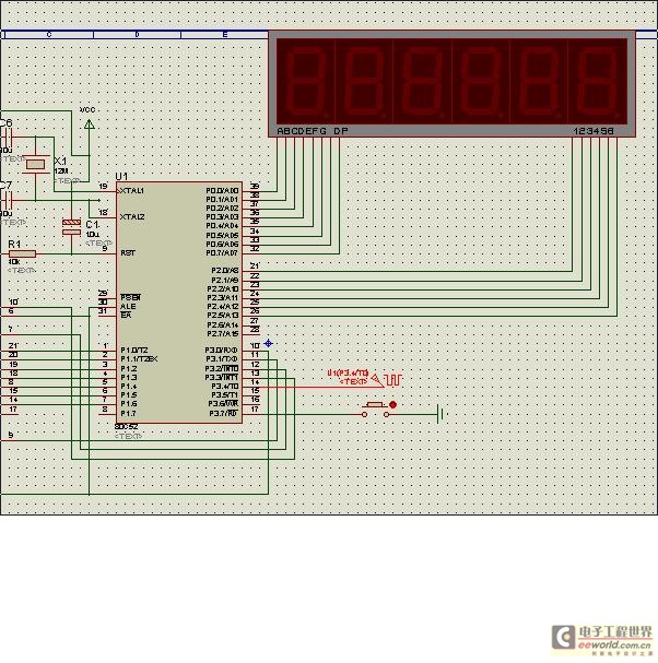
The 7208 seven-stage decimal counter can be utilized as a frequency counter. It features latch and multiplexing functions, along with direct digital driving circuitry and display driving circuitry. The output frequency of the 7207 IC 6.5536 MHz crystal oscillator...
Warning: include(partials/cookie-banner.php): Failed to open stream: Permission denied in /var/www/html/nextgr/view-circuit.php on line 713
Warning: include(): Failed opening 'partials/cookie-banner.php' for inclusion (include_path='.:/usr/share/php') in /var/www/html/nextgr/view-circuit.php on line 713