
Balanced Microphone Preamplifier
This preamplifier circuit is primarily based on the NE5534 op-amp, which is known for its low noise and high-performance characteristics, making it suitable for audio applications. The balanced input design is crucial for minimizing noise and interference, especially in professional audio settings. The use of matched resistor pairs (R1-R4 and R2-R5) ensures that any common-mode signals are effectively rejected, enhancing the overall fidelity of the audio signal.
The inclusion of the preset potentiometer P1 allows for fine-tuning of the common-mode rejection ratio, which is critical in environments where electromagnetic interference may be present. The capacitor C1 plays a vital role in protecting the op-amp from any DC offset that may be present at the microphone output, thus ensuring that only the AC audio signal is amplified. Resistor R7 is essential for maintaining stability when driving capacitive loads, which can otherwise lead to undesirable oscillations.
R3 serves a dual purpose; while it can be omitted in cases where the microphone cable length provides sufficient parasitic capacitance, its inclusion significantly boosts the CMR, thereby improving the overall performance of the preamplifier. The performance metrics indicate that this circuit can handle low-level signals with high fidelity, making it ideal for use in high-quality audio recording and amplification systems.
The power supply configuration of ±15 V is standard for many op-amp circuits, providing sufficient headroom for audio signals while keeping the current consumption at a manageable level. The current draw of 5.5 mA indicates that this circuit is energy-efficient, which is beneficial for battery-operated or portable applications.
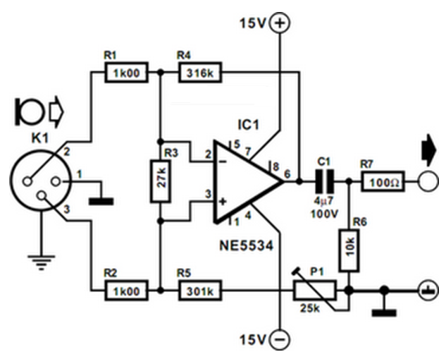
Finally, the decoupling of the supply lines with inductors L1, L2, and capacitors C2, C5 is a critical design consideration that helps to filter out any power supply noise, ensuring that the op-amp operates with a clean and stable voltage. This attention to detail in the power supply design further enhances the reliability and performance of the preamplifier circuit.The preamplifier is intended for use with dynamic (moving coil MC) microphones with an impedance up to 200 © and balanced terminals. It is a fairly simple design, which may also be considered as a single stage instrument amplifier based on a Type NE5534 op amp.
To achieve maximum common-mode rejection (CMR) with a balanced signal, the division ratios of the dividers (R1-R4 and R2-R5 respectively) at the inputs of the op amp must be identical. Since this may be difficult to achieve in practice, a preset potentiometer, P1, is connected in series with R5. The preset enables the common-mode rejection to be set optimally. Capacitor C1 prevents any direct voltage at the input, while resistor R7 ensures stability of the amplifier with capacitive loads.
Resistor R3 prevents the amplifier going into oscillation when the input is open circuit. If the microphone cable is of reasonable length, R3 is not necessary, since the parasitic capacitance of the cable ensures stability of the amplifier. It should be noted, however, that R3 improves the CMR from >70 dB to >80 dB. Performance of the preamplifier is very good. The THD+N (total harmonic distortion plus noise) is smaller than 0. 1% with an input signal of 1 mV and a source impedance of 50 ©. Under the same conditions, the signal-to-noise ratio is 62. 5 dBA. With component values as specified, the gain of the amplifier is 50 dB ( 316). After careful adjustment of P1 at 1 kHz, the CMR, without R3, is 120 dB. The supply voltage is ±15 V. The amplifier draws a current at that voltage of about 5. 5 mA. Note the decoupling of the supply lines with L1, L2, C2 C5. 🔗 External reference
Related Circuits
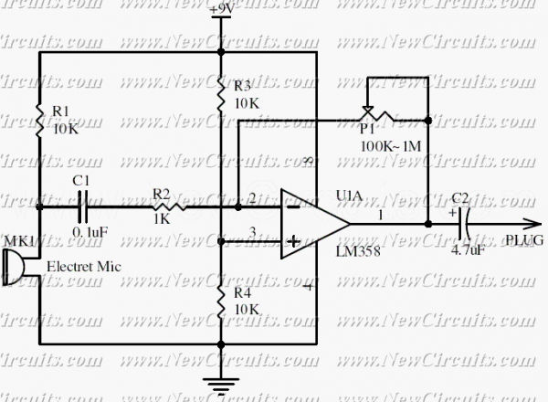
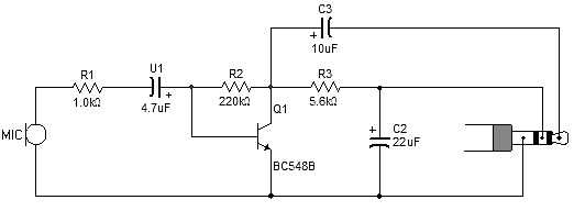
This circuit will be useful if you have an electret microphone that produces a low audio (sound) level and you want to connect it to an amplifier or something like it. The circuit boosts the microphone output voltage to...
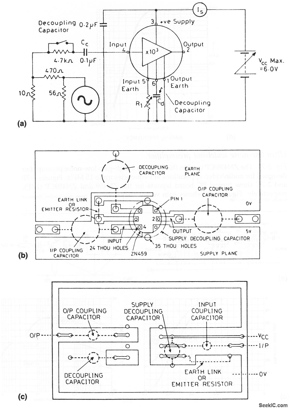
The ZN459/CP utilized in this circuit is a high-gain, low-noise preamplifier intended for audio and video applications at frequencies reaching up to 15 MHz. Figures 2-7B and 2-7C illustrate typical printed circuit board layouts for the ZN459 and ZN459CP...
The design consists of differential compound pairs of transistors with a common mode (floating) gain control connecting the emitters of the pair. The compound pairs of 2N4403 and BC549s are far more linear than any single transistor. The circuit...
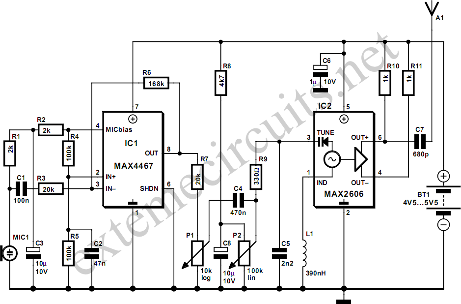
This project involves a simple and cost-effective transmitter that allows for speech transmission over a short range, functioning effectively as a cordless microphone. The circuit utilizes two integrated circuits from Maxim. The first, IC1, is the MAX4467, which amplifies...
This circuit diagram represents an ECM Mic Preamplifier. It is a microphone amplifier compatible with Electret Condenser Microphones (ECM). The preamplifier exhibits an excellent dynamic range, capable of handling audio levels from a whisper to a scream; however, caution...
Most sound card microphone inputs require a minimum signal level of at least 10 millivolts, but some older 8-bit cards need as much as 100 millivolts. The typical impedance of the PC sound card microphone input is in the...