
Blinker circuit 2
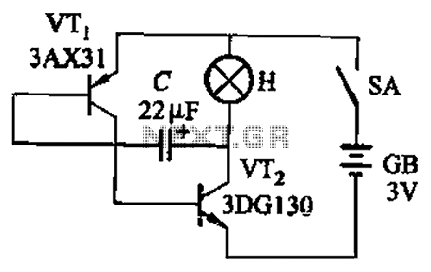
This circuit employs a pair of transistors, VTi and VTz, configured in a feedback loop facilitated by capacitive coupling through capacitor C. The operation relies on the triode characteristics of the transistors, which allow them to switch states based on the voltage levels across the capacitor. When VTi turns on, it allows current to flow through the circuit, charging the capacitor C. Once the capacitor reaches a certain voltage threshold, it triggers the turn-off of VTi and the turn-on of VTz. This process causes the light to flash.
The flash frequency is primarily determined by the time constant of the RC circuit formed by the capacitor C and the resistance in the circuit, which includes the load and any resistors present. The capacitance value of C, in conjunction with the current flowing through VTi, dictates how quickly the capacitor charges and discharges, thus influencing the overall flashing frequency. For the specified configuration, the circuit is designed to achieve a flashing frequency of around 20 flashes per minute, which can be adjusted by varying the capacitance or the current supplied to the circuit.
This design is particularly useful in applications where visual signaling is required, such as in decorative lighting or alert systems. The simplicity of the circuit allows for easy implementation and adjustment, making it a versatile choice for various electronic projects. Circuit shown in Figure 13-4. It uses triode control. Two transistors VTi, VTz by capacitive coupling C, so that they alternately turn on and off, so that H produce flash light s sparkle. Flash frequency capacity ,. and c is determined by the capacitance of the transistor VTi through current I. Press the element in FIG values lamp flash frequency of about 20 times per minute.
Related Circuits
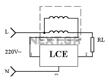
This is an application circuit of the device as illustrated in principle. In the meter, the voltage and current coils are connected to the power line, regardless of whether a load is connected. The voltage coil consistently draws power,...
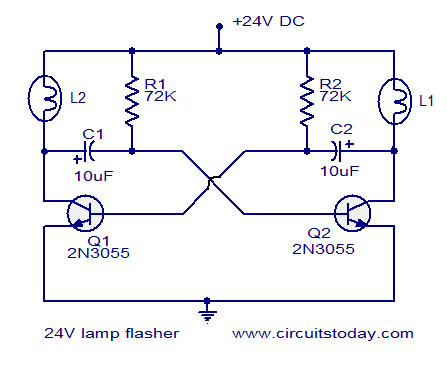
The circuit operates on 24V DC and is designed to alternately flash two 24V bulbs. It functions as an astable multivibrator with a frequency of 1Hz and a duty cycle of 50%. The lamps to be flashed are connected...
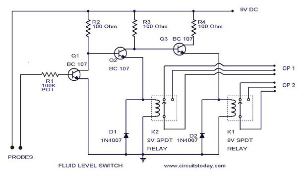
A simple liquid level switch circuit with diagram and schematic. This can also be used as a water level switch, fluid level switch, float level switch, and tank level switch. The liquid level switch circuit is designed to detect the...
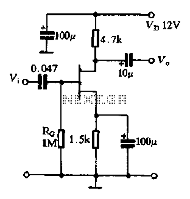
The FET exhibits a high input impedance, a low noise figure, anti-crosstalk capabilities, and good mutual interference performance, making it increasingly utilized in electronic circuits. FET amplifiers can be configured in various ways, including as common source (equivalent to...
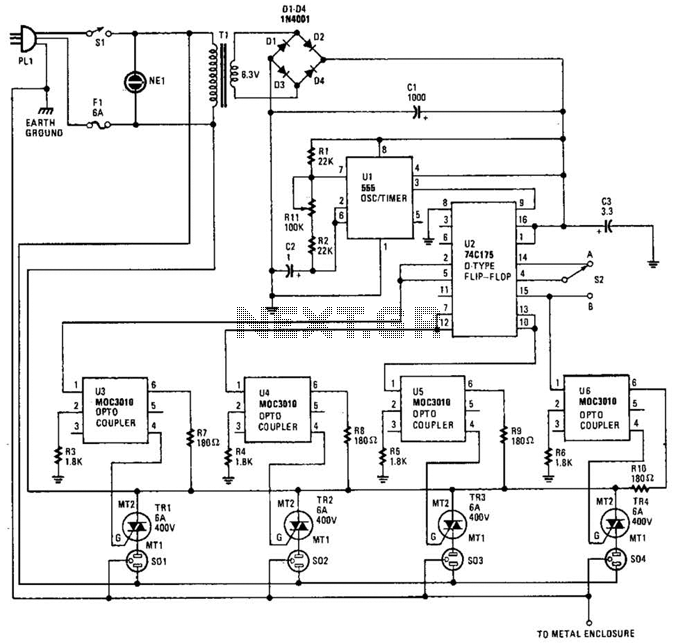
The integrated circuit U1 (a 555 oscillator/timer) is configured as a conventional pulse generator. The frequency of the pulse generator is adjusted using potentiometer R11. Resistor R2 limits the maximum frequency attainable. The output from the pulse generator is...
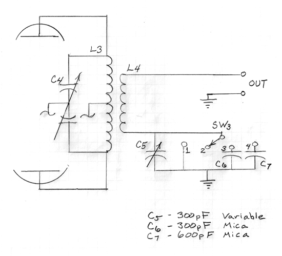
A series capacitor is most effective for low impedance loads, while a parallel capacitor is utilized for high impedance loads. The current standard is a 50-ohm antenna and coax system that requires a series capacitor for loading adjustment. With...