
Liquid/Fluid/Water/Float/Tank Level SwitchCircuit using Relay
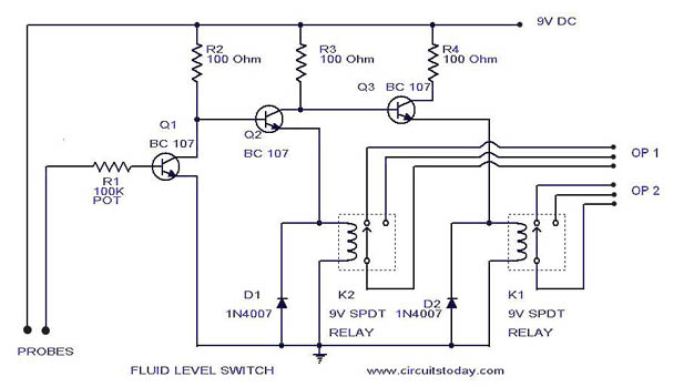
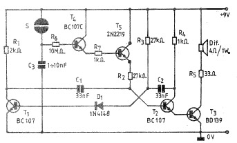
The liquid level switch circuit is designed to detect the presence or absence of liquid within a tank or container. This type of circuit can be employed in various applications, such as water level control in reservoirs, fluid level monitoring in industrial processes, and float level detection in aquariums or sump pumps.
The basic configuration of a liquid level switch typically consists of a float mechanism, a switch (often a reed switch or a mechanical switch), and a power supply. The float is buoyant and moves up and down with the liquid level. When the liquid level reaches a predetermined point, the float activates the switch, which can then trigger an alert, control a pump, or turn on/off an indicator.
In the schematic diagram, the float is connected to the switch, which is in turn connected to a power source and the load (such as a pump or an alarm). The circuit may include additional components such as resistors, diodes, or capacitors to enhance performance, provide protection against voltage spikes, or filter noise.
For enhanced versatility, the circuit can be designed to operate in both normally open (NO) and normally closed (NC) configurations, allowing for customization based on the specific application requirements. The use of microcontrollers or programmable logic controllers (PLCs) can further improve functionality by enabling more complex control algorithms and integration with other systems.
Overall, this liquid level switch circuit is a fundamental yet essential component in fluid management systems, providing reliable and effective monitoring and control of liquid levels.A simple liquid level switch circuit with diagram and schematic.This can also be used as water level switch,fluid level,float level and tank level switch.. 🔗 External reference
Related Circuits

The circuit illustrated below represents a simple thermometer circuit based on the LM335 temperature sensor. This circuit comprises two main components: the LM335 sensor and its adjustment circuitry. The output from the LM335 generates a voltage of 10 millivolts...
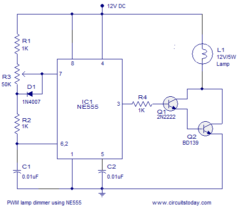
A simple PWM lamp dimmer using the NE555 timer IC. The 555 timer IC is configured as a variable duty cycle astable multivibrator to control the brightness of the lamp. The described circuit utilizes the NE555 timer IC, a versatile...
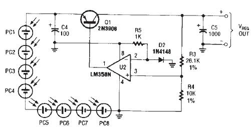
The circuit diagram illustrates a portable solar charger that utilizes an LM358N operational amplifier and a single transistor. This regulator delivers a constant output of 2.4 volts DC, suitable for powering small devices requiring energy from two AA battery...
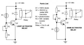
The potentiometer adjusts the trigger level. The diode in the circuit diagram is specified as 1N914, which is suitable for light-duty relays; however, since the 1N914 is a signal diode, it is not ideal. A 1N4001 or a better...
AN6884 is a logarithmic scale LED bar display driver that accepts a wide range of supply voltages, from 3.5V to 16V. This device is designed for use in voltage unit (VU) bar displays. The AN6884 is specifically engineered to drive...
A simple and practical electronic bell circuit can be constructed using the provided schematic diagram. This circuit can function as a doorbell or an alarm system. It utilizes only a few transistors along with several common components. The circuit...
Warning: include(partials/cookie-banner.php): Failed to open stream: Permission denied in /var/www/html/nextgr/view-circuit.php on line 713
Warning: include(): Failed opening 'partials/cookie-banner.php' for inclusion (include_path='.:/usr/share/php') in /var/www/html/nextgr/view-circuit.php on line 713