
Connection of the stator coils b

The stator coils in an electric machine are crucial components that generate the magnetic field necessary for operation. The triangular (delta) and star (wye) configurations are two common methods for connecting these coils.
In a triangular connection, each coil is connected end-to-end, forming a closed loop that allows for higher voltages and is typically used in applications requiring higher starting torque. This configuration can be advantageous in scenarios where the power supply can handle the increased voltage, as it allows for a more robust current flow through the coils.
Conversely, the star connection involves connecting one terminal of each coil to a common point, while the other terminals are connected to the power supply. This configuration is often preferred for its ability to reduce the starting current and provide a smoother operation, making it suitable for applications where a gradual increase in torque is desired.
In practical applications, the choice between triangular and star connections depends on various factors, including the specific requirements of the motor, the nature of the load, and the characteristics of the power supply. Understanding these configurations allows engineers to optimize the performance and efficiency of electric machines in various industrial and commercial applications.Connection of the stator coils b Shows the structure and connections of the stator coil, and FIG. (A) shows a triangular connection, Figure (b) shows a star connection, star co nnection in two forms.
Related Circuits
A low resistance (0.25 - 4 ohm) continuity tester for checking soldered joints and connections. This simple circuit uses a 741 op-amp in differential mode as a continuity tester. The voltage difference between the non-inverting and inverting inputs is...
This is a simple circuit for automatic switchover between battery and USB port. This circuit uses a more general step-up converter architecture. The circuit designed for automatic switchover between a battery and a USB power source employs a step-up...
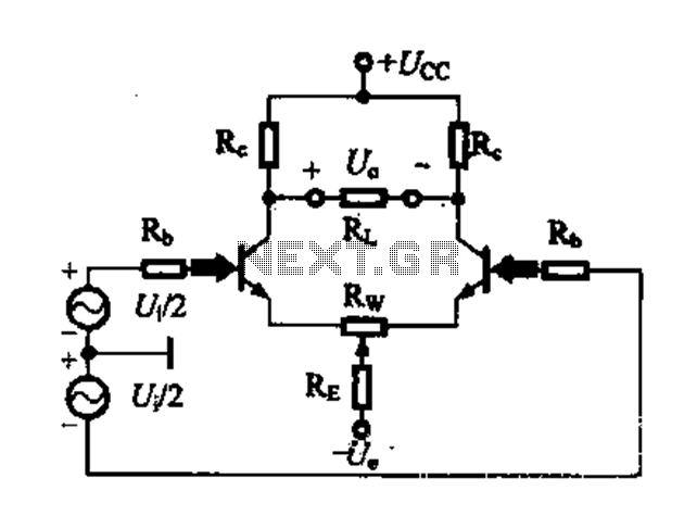
A differential amplifier circuit can be configured in four different connection methods, allowing for a comparison of characteristics such as gain and common-mode rejection ratio (CMRR). This analysis focuses on symmetrical circuits and their performance in handling common-mode signals. The...
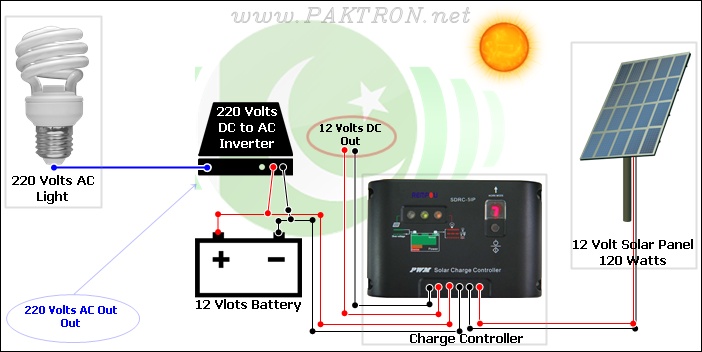
A solar charge controller is an electronic device used in solar system installations to regulate the amount of charge directed toward a battery from a solar panel. Charge controllers come in various types and ratings. The term "charge controller"...
This simple circuit employs a 741 operational amplifier (op-amp) in differential mode to function as a continuity tester. The voltage difference between the non-inverting and inverting inputs is amplified by the full open-loop gain of the op-amp. Initially, ignore...
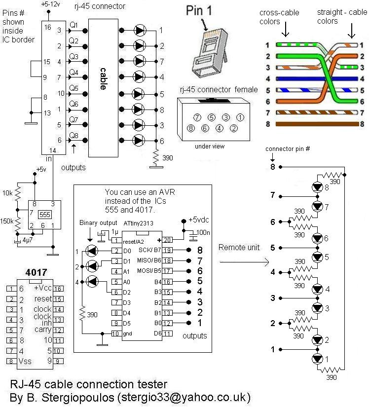
Here is a very simple yet practical circuit designed to check the type of LAN cables (straight or cross) as well as to identify possible faults. The circuit utilizes a unit with 8 outputs, each producing a pulse successively,...