
LAN RJ45 Cable Connection Tester

The circuit operates by sequentially activating each output pin to send a pulse through the LAN cable. The main board contains a microcontroller, such as the AVR ATtiny2313, which is programmed to generate a series of pulses. The design ensures that only one output is active at any time, creating a clear and distinct signal that travels through the connected LAN cable.
When a straight LAN cable is used, the signal travels directly from one connector to the other, illuminating the LEDs in the order they are connected. This allows for a straightforward visual indication of the cable's integrity. If any of the internal wires are broken, the corresponding LED will remain off, indicating a fault in the cable.
In contrast, when a cross-over cable is connected, the internal wiring configuration changes the path of the signals, resulting in a different sequence of illuminated LEDs. This change can be utilized to quickly identify the type of cable being tested without the need for additional equipment.
For remote testing, the circuit can be extended using a secondary board equipped with LEDs. This remote unit connects to one end of the LAN cable, while the main board remains at the other end. The design of the remote unit eliminates the need for a common ground wire, simplifying the connection process.
This circuit is not only useful for checking LAN cables but can also serve as an educational tool for understanding the differences between straight-through and cross-over cables. The use of an AVR microcontroller allows for flexibility in design and the potential for further enhancements, such as incorporating additional features or a more sophisticated user interface.Here`s a very simple, but practical circuit, which is used to check the type of LAN cables (straight or cross) as well as possible faults. So we use a unit that has 8 outputs, each one of which produces a pulse successivly. Only one output can be high at any time. Then we use two rj45 connectors and we apply the pulses to the 8 pins of one connect or (A) wnd we connect LEDs at the pins of the other connector (B). If we connect a straight LAN cable, we notice that the LEDs glow one by one successively. If a wire is broken, the coresponding LED will not glow. Just watch the LEDs. If we connect a cross wire, then the order of LEDs glowing changes to 1, 2, 7, 4, 5, 8, 3, 6. So we can laber the LEDs in that order, so that we can watch easily. If both ends of the cable are not close enough to be pluged onto the curcuit, we can use an remote board, which has only one rj-45 connector and 8 LEDs. Then plug one end of the cable to connector A on main board and connect the other end to the remote unit.
Notice that no common wire is needed for the remote unit. I have included an alternative circuit instead of using classic ics, I use the AVR ATtiny2313, but any AVR controller can be easily adapted. See photo and diagram. 🔗 External reference
Related Circuits
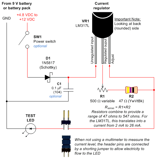
Most circuits utilize a 5 V regulated power supply for microcontrollers and sensors, as 8-bit microcontrollers operate efficiently at this voltage. The 5 V supply is adequate for powering white LEDs, thus the specific voltage requirements of individual LEDs...

This project utilizes a microcontroller that is programmed with software available on the Gernsback BBS at 516-293-2283 as part of RUNABOUT.ZIP. The robot can be operated using a universal remote control. The project involves the integration of a microcontroller, which...

The indicator provides an accurate comparison of two voltages by indicating their degree of balance or imbalance. Detecting small variations near the null point is challenging with the basic Wheatstone bridge alone. Amplifying voltage differences near the null point...
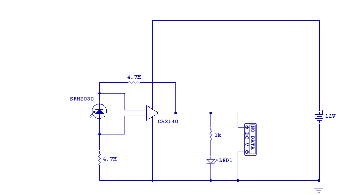
As I was developing my IR Extender Circuit, I needed to find a way of measuring the relative intensities of different Infra red light sources. This circuit is the result of my research. I have used a photodiode, SFH2030...
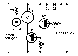
The above circuit can be useful to detect if the load of any battery charger or plug-in adaptor supply is not properly connected. The load can be a set of batteries to be charged or any other type of...

This power inverter circuit provides a stable square wave output voltage. The frequency of operation is set by a potentiometer and is typically adjusted to 60 Hz. Various off-the-shelf transformers can be utilized, or custom-wound transformers can be created...