
Electric shaver circuit

The electric shaver circuit operates by utilizing a buck converter topology to efficiently step down the voltage from the power supply. The buck capacitor (C) plays a crucial role in smoothing out the voltage and ensuring stable operation of the circuit. The diode (VD) is essential for allowing current to flow in one direction, thereby preventing backflow that could damage the circuit components, particularly when charging the nickel-cadmium batteries.
The integration of an LED display serves as a visual indicator of the shaver's operational status, enhancing user interaction. The LED illuminates when the device is powered on, providing a clear signal that the shaver is ready for use. The toggle switch (S) enables the user to easily control the power to the motor, which is responsible for the rotational motion necessary for effective shaving.
When the shaver is not in operation, it remains connected to a 220V power source for charging. This design choice ensures that the nickel-cadmium batteries are continuously charged and ready for use, promoting convenience and ensuring the device is always operational when needed. The motor, upon activation, engages the shaver head, allowing for efficient hair removal through its rotational motion. The overall circuit design emphasizes safety, efficiency, and user-friendliness, making it suitable for everyday grooming needs.Electric shavers thorn circuit shown in Figure 1-17. Shown by the capacitance C buck, buck capacitor C is lyF/450V, pass through the diode VD, to 1.2V nickel-cadmium batteries. After Buck Island for the display element to the LED. When not in use, connected to the 220V power charger, so when used, toggle switch S, and the motor is turned on, the motor drives the shaver piece rotation.
Related Circuits
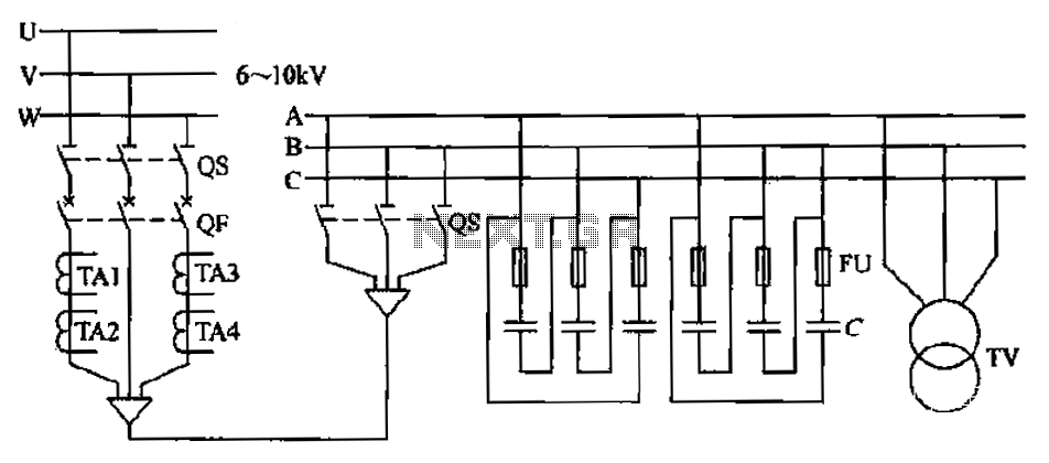
The compensation system is designed to focus on a high-pressure, high-voltage capacitor bank installed in the substation 6-10 kV bus. Compensation can only be implemented in this manner for the 6-10 kV bus before the reactive power on the...

This article discusses the functionality of a super-regenerative FM receiver. The principle behind this receiver utilizes high-gain miniature integrated circuits, resulting in a simple and innovative circuit design. It achieves the performance level of standard FM receivers while addressing...

This LED flasher circuit is a classic two-transistor flip-flop. It is a popular circuit often built by beginners in the electronics hobby. The schematic diagram of this well-known LED flasher circuit includes two transistors, two capacitors, four resistors, and...

IC1-c functions as a non-inverting comparator, while IC1-a operates as an inverting comparator. Potentiometer R1 and fixed resistors R2 and R3 create a voltage divider chain that provides slightly different voltages to the two comparators. These voltages establish the...
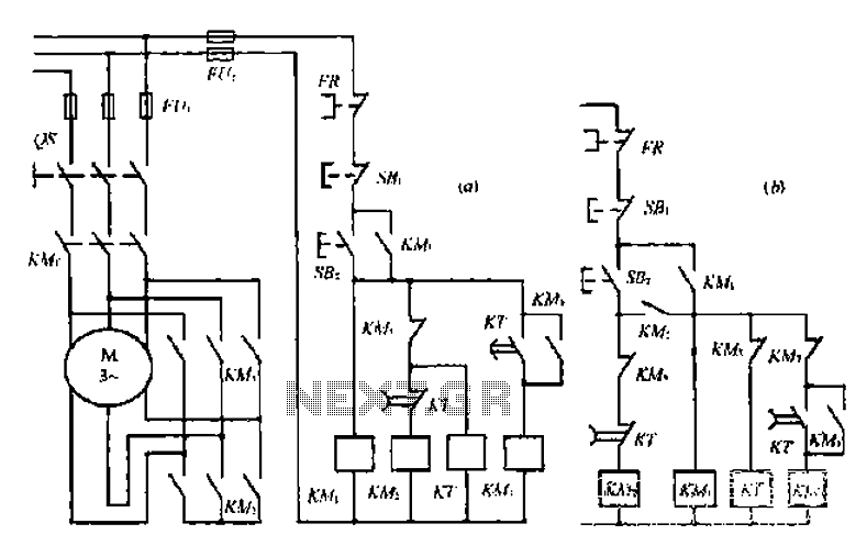
A star-delta switch is utilized for starting circuits, commonly depicted in Figure I-5 (a) of the knife wiring. While this method is effective, it poses security risks. When the motor starts, it can create significant voltage fluctuations that may...

A dual-tone model train horn/sound generator/simulator circuit can be created using two NE 555 timers connected in cascade. However, the circuit diagram presented is designed with the NE 556 integrated circuit, which essentially comprises two 555 timers in a...