
classic led flasher circuit
The LED flasher circuit operates on the principle of a bistable multivibrator, utilizing two NPN transistors configured in a feedback loop. The circuit's functionality hinges on the charging and discharging cycles of the capacitors, which directly influence the timing of the LED flashes. Each transistor's base is connected to a resistor that limits the current, ensuring safe operation and preventing damage to the components.
Upon initial power application, one transistor receives a slight edge in triggering due to minor variations in component characteristics, causing it to turn on first. This action results in the LED connected to that transistor illuminating. The activated transistor pulls the base of the other transistor low through the capacitor, preventing it from turning on. As the capacitor connected to the first transistor charges, it eventually reaches a threshold voltage, allowing the second transistor to conduct and subsequently illuminating its associated LED.
The time taken for each LED to flash is governed by the RC time constant, which is the product of the resistance (R) and capacitance (C) values in the circuit. By adjusting these values, users can customize the flashing frequency to suit their preferences. For instance, increasing the capacitance will prolong the charging time, resulting in a slower flashing rate, while reducing capacitance will yield a faster flash rate.
This circuit serves as an excellent introduction to fundamental electronic concepts, including transistor operation, timing circuits, and the behavior of capacitors in RC networks. It provides hands-on experience with basic electronic components and is a valuable learning tool for those new to electronics.This LED flasher circuit is a classic two transistor flip flop. This flasher circuit is very popular and it`s usually the first circuit to build when starting electronic circuit building hobby. Here is the schematic diagram of the famous LED flasher circuit: The circuit consist of two transistors, two capacitors, four resistors, and two LEDs.
When the power supply is first connected to this LED flasher circuit, both transistor is racing to be triggered first by the base current through 100k resistor. Actually when one transistor is triggered first than the other, the first activated transistor will behave like a closed switch, so the LED will turn ON and the base of the other transistor will be grounded through the capacitor.
This grounding keep the first transistor to be activated and the second one to stay off untill the capacitor is charged above the bias voltage needed to activate the second transistor. After reaching this voltage, the second transistor will be switched on and now the second transistor will turn ON the LED on its collector, turning off the first transistor by grounding its base through the second capacitor.
This alternating process will be repeated forever until the power supply is turned off. The flashing rate will depend on the resistors (100k) and the capacitors values. You can change the values of the capacitors to change the flashing frequency. Use a higher capacitance value for lower flashing rate, and vice verse. 🔗 External reference
Related Circuits
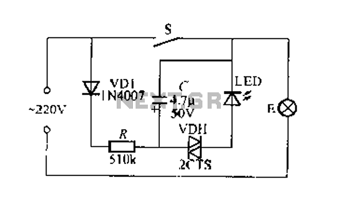
Figure 2 illustrates a circuit for a flashing light switch indicator. When switch S is closed, the normal light E illuminates, while the flashing light indicates a power loss when the system is not operational. When switch S is...
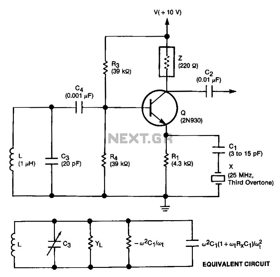
This unit is easily tunable and stable, consumes minimal power, and is more cost-effective than other types of oscillators that operate at similar frequencies. This unique combination of features is made possible by a design concept that involves operating...
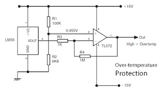
This is a basic overview of the LM35 temperature sensor, which is interfaced with an operational amplifier (op-amp) to boost its output. The LM35 provides a high output voltage when it detects high temperatures. The output can be utilized...
The heating element is connected in series with two back-to-back 16 amp silicon-controlled rectifiers (SCRs), which are controlled by a small pulse transformer. This pulse transformer features three identical windings: two are dedicated to providing trigger pulses to the...

This is a simple automatic light switch circuit designed for bedrooms. After construction, connect the input terminals of this circuit in parallel to the existing light fixture. The automatic light switch circuit operates using a photoresistor (LDR) and a transistor...
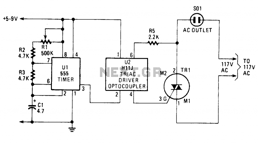
The blinking or flashing rate is determined by U1, a 555 timer integrated circuit. Its output, at pin 3, feeds U2, a H11J triac driver. That driver consists of an infrared LED that is coupled internally to a light-activated...