
OTL tube amp amplifier production
The 6N5P tube is a versatile component in audio amplifier designs, particularly in configurations that require low output impedance. In a parallel push-pull arrangement, multiple tubes work together to improve efficiency and reduce distortion. Each tube in the setup contributes to a lower overall output impedance, which is critical for driving speakers effectively.
The circuit design includes an output transformer that can be omitted if a dual power supply is implemented. This allows for a more compact design and potentially improves the overall fidelity of the amplifier by reducing the number of components that can introduce noise or signal degradation.
The biasing of the tubes is vital for optimal performance. The use of RP1 and RP2 allows for fine-tuning of the operating point of the tubes, ensuring that they function within their linear range. This adjustment is crucial for achieving the desired sound quality and preventing distortion during operation.
In practical applications, the multimeter serves as a diagnostic tool to monitor the voltage drop across the resistor, which is indicative of the current flowing through the circuit. Setting the drop to 0.2V is a typical procedure to ensure that the tubes are operating correctly and within specified parameters.
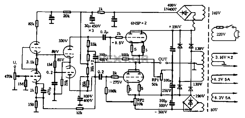
Overall, the described circuit configuration with the 6N5P tubes is designed to deliver high-quality audio performance while maintaining simplicity and efficiency in its design. The careful selection of components and the adjustment of biasing resistors play a significant role in achieving the desired audio characteristics.6N5P the output impedance of 400 ohms low resistance tube used as a parallel push-pull, the output impedance of a single tube half, and then two-three-plate and pipe used in pa rallel, the impedance will be further reduced, it can be removed from the output transformer used double supply and reasonable bias position adjustment, can be removed from the output capacitor, the whole circuit is shown in Figure 1-33. The figure shows the operating voltage o RPl between levels. RP2 set maximum resistance for adjusting the final stage and screen flow midpoint output. Multimeter set 1V block were measured and down tube 5 (! Voltage across the resistor, adjust RP1, RP2 so drop across the resistor 0.2V.
Related Circuits
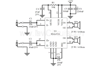
This document presents a 22-watt stereo audio power amplifier circuit diagram based on the TDA1554 integrated circuit from NXP Semiconductors (formerly Philips Semiconductors). The 22-watt stereo audio power amplifier circuit utilizing the TDA1554 IC is designed to deliver high-quality audio...
In linear equipment design, it is sometimes necessary to take a voltage that is referenced to a certain DC level and generate an amplified output that is also referenced. In linear circuit design, the process of amplifying a voltage that...
This project is one for the experimenter, but as shown will work extremely well. The sensing circuit can be made so sensitive that a load of only 2.5mA is enough for the circuit to detect, and disconnect the charger....
This phono stage significantly outperformed a sub-mini phono preamp. The phono preamp was exceptionally quiet when paired with a vintage Grado 8MR cartridge (not MC). It does not have a vintage sound; while it is pleasant and clearly tube-based,...
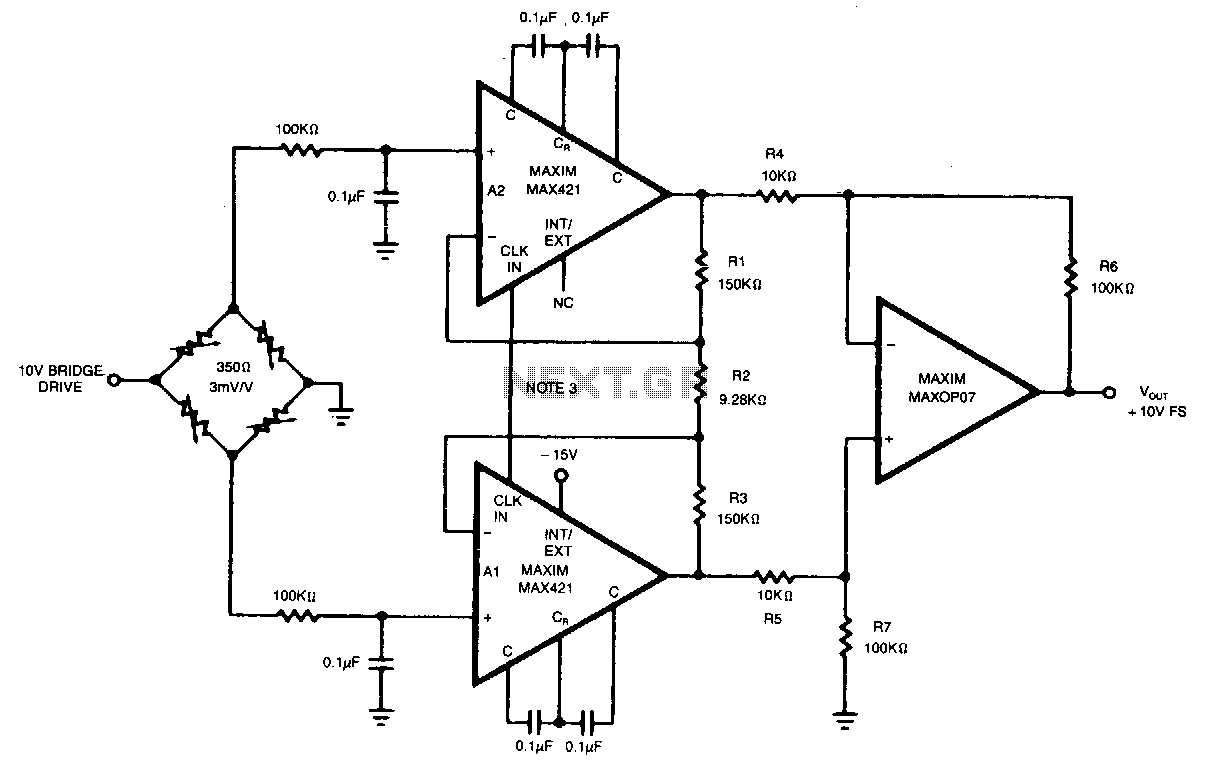
This circuit achieves an overall gain of 320. Additional gain can be obtained by decreasing the value of R2. The untrimmed Vas is 10.11V, and the Vas temperature coefficient is less than 0.1µV/°C. In various applications, the OP07 can...
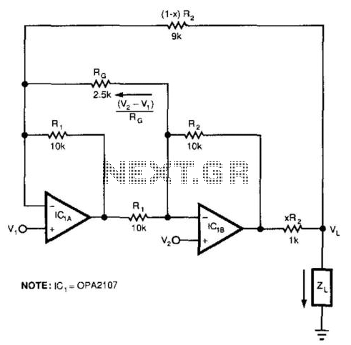
This circuit responds to the difference between Vj and V2. Rq sets the gain. Resistors XR2 and (1 - X) R2 produce the bootstrap effect. These two resistors convert the circuit's output voltage to a current. IC1 and IC2...