
22W Stereo Amplifier Using TDA1554
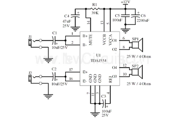
The 22-watt stereo audio power amplifier circuit utilizing the TDA1554 IC is designed to deliver high-quality audio amplification for various applications, such as home audio systems, car audio systems, and portable speakers. The TDA1554 is a dual-channel power amplifier that can provide up to 22 watts of output power per channel, making it suitable for driving speakers with moderate power requirements.
The circuit typically consists of the TDA1554 IC, which incorporates several key features, including thermal protection, short-circuit protection, and a built-in mute function. The amplifier operates in class AB mode, which ensures low distortion and high efficiency, contributing to superior sound quality.
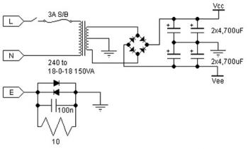
In the schematic, the power supply section is crucial for the amplifier's performance. The TDA1554 operates with a supply voltage range of 12V to 28V, allowing flexibility in power supply design. Proper decoupling capacitors are essential to filter out noise and stabilize the power supply, ensuring reliable operation.
Input signals are usually fed into the amplifier through a coupling capacitor, which blocks any DC component, allowing only the AC audio signal to pass. The gain of the amplifier can be adjusted by configuring external resistors, enabling customization based on specific application requirements.
Output connections are made to the speakers, with considerations for impedance matching to optimize performance. The circuit may also include additional components such as feedback resistors and capacitors to enhance stability and frequency response.
Overall, this amplifier circuit design provides an effective solution for audio amplification needs, combining efficiency and sound fidelity, making it a popular choice for audio enthusiasts and professionals alike.Here is the 22 watt stereo audio power amplifier circuit diagram based on TDA1554 and integrated circuit from NXP semiconductors (formerly PHILIPS semicon.. 🔗 External reference
Related Circuits
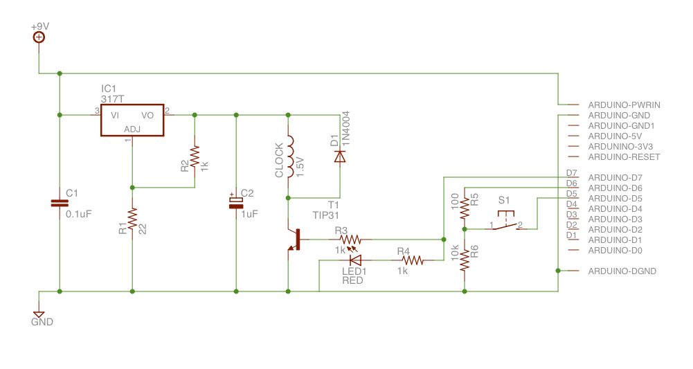
Upon purchasing the slave dial, it arrived without instructions, packaging, or additional details. The only visible markings, aside from decades of grime, were on the face (SMITH SECTRIC, ACELEC SYDNEY) and some markings on the bracket holding the mechanism...
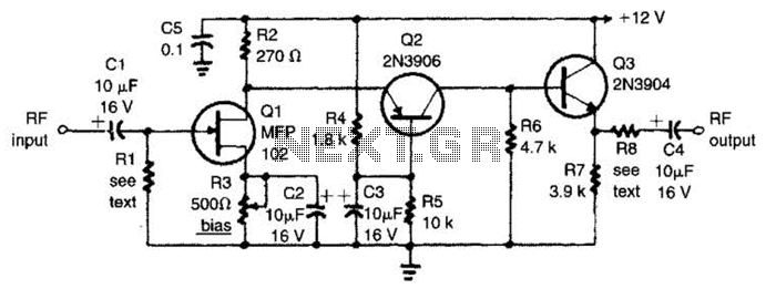
The circuit features a frequency response that spans from 100 Hz to 3 MHz, with a gain of approximately 30 dB. Field-effect transistor Q1 is arranged in a common-source self-biased configuration, and an optional resistor R1 is available to...
Can be directly connected to CD players, tuners and tape recorders. The circuit described above can be interfaced directly with various audio devices such as CD players, tuners, and tape recorders. This indicates that the circuit is designed to handle...

The SL561 utilized in this circuit functions as a high-gain, low-noise preamplifier intended for audio and video applications at frequencies reaching up to 6 MHz. Figure 2-6B illustrates the gain in relation to frequency for different capacitance values of...
A 30W Class AB power amplifier circuit diagram utilizes a power transistor. To set up the amplifier, adjust the variable resistor R1 to its maximum value and R12 to zero. After completing this setup, activate the amplifier. Adjust R1...
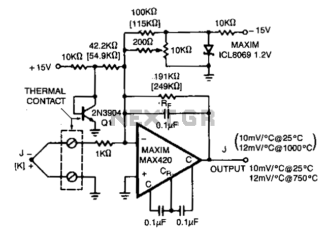
The MAX420 is operated at a gain of 191 to convert the 52 µV/°C output of the type J thermocouple to a 10 mV/°C signal. The -2.2 mV/°C temperature coefficient of the 2N3904 is added into the summing junction...