
Over-Under Voltage Cut-Out with 555
The circuit operates using two 555 timer ICs configured in a comparator mode. The first IC (IC1) is responsible for monitoring under-voltage conditions, while the second IC (IC2) handles over-voltage conditions. The voltage thresholds are set using variable resistors (VR1 and VR2), which allow for precise adjustment of the cut-off points. The reference voltage for the comparators is derived from the supply voltage (Vcc), divided down to 1/3 Vcc for comparison against the input voltage.
When the input voltage drops below the preset under-voltage threshold (e.g., 160V AC), the output of IC1 goes high, triggering transistor T1, which in turn pulls the reset pin of IC2 low, disabling its output. Conversely, if the input voltage exceeds the over-voltage threshold (e.g., 270V AC), the output of IC2 goes low, cutting off transistor T2 and de-energising the relay (RL1), thereby disconnecting the load from the power supply.
The use of LEDs as indicators provides visual feedback for the operational status of the circuit, with LED1 indicating under-voltage and LED2 indicating over-voltage conditions. The circuit is designed for automatic reset, meaning that once the voltage returns to safe levels, the relay will re-energise without manual intervention. This feature enhances the reliability of the circuit, protecting sensitive electronics from voltage fluctuations. Overall, the design ensures that electrical appliances are safeguarded against potentially damaging voltage levels, promoting longevity and performance. This over/under voltage cut-out will save your costly electrical and electronic appliances from the adverse effects of very high and very low mains voltages. The circuit features auto reset and utilises easily available components. It makes use of the comparators available inside 555 timer ICs. Supply is tapped from different points of the power supply circuit for relay and control circuit operation to achieve reliability.
The circuit utilises comparator 2 for control while comparator 1 output (connected to reset pin R) is kept low by shorting pins 5 and 6 of 555 IC. The positive input pin of comparator 2 is at 1/3rd of Vcc voltage . Thus as long as negative input pin 2 is less positive than 1/3 Vcc, comparator 2 output is high and the internal flip-flop is set, i.e.
its Q output (pin 3) is high. At the same time pin 7 is in high impedance state and LED connected to pin 7 is therefore off. The output (at pin 3) reverses (goes low) when pin 2 is taken more positive than 1/3 Vcc. At the same time pin 7 goes low (as Q ouptput* of internal flip- flop is high) and the LED connected to pin 7 is lit. Both timers (IC1 and IC2) are configured to function in the same fashion. Preset VR1 is adjusted for under voltage (say 160 volts) cut-out by observing that LED1 just lights up when mains voltage is slightly greater than 160V AC.
At this setting the output at pin 3 of IC1 is low and transistor T1 is in cut-off state. As a result RESET* pin 4 of IC2 is held high since it is connected to Vcc via 100 kilo-ohm resistor R4. Preset VR2 is adjusted for over voltage (say 270V AC) cut-out by observing that LED2 just extinguishes when the mains voltage is slightly less than 270V AC.
With RESET* pin 4 of IC2 high, the output pin 3 is also high. As a result transistor T2 conducts and energises relay RL1, connecting load to power supply via its N/O contacts. This is the situation as long as mains voltage is greater than 160V AC but less than 270V AC. When mains voltage goes beyond 270V AC, it causes output pin 3 of IC2 to go low and cut-off transistor T2 and de-energise relay RL1, in spite of RESET* pin 4 still being high.
When mains voltage goes below 160V AC, IC1s pin 3 goes high and LED1 is extinguished. The high output at pin 3 results in conduction of transistor T1. As a result collector of transistor T1 as also RESET* pin 4 of IC2 are pulled low. Thus output of IC2 goes low and transistor T2 does not conduct. As a result relay RL1 is de-energised, which causes load to be disconnected from the supply. When mains voltage again goes beyond 160V AC (but less than 270V AC) the relay again energises to connect the load to power supply. 🔗 External reference
Related Circuits
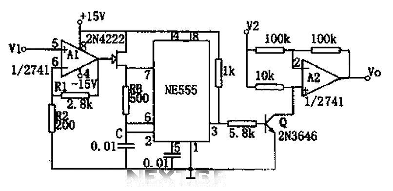
The circuit depicted in the figure consists of a voltage-frequency converter and an amplitude modulator. The input voltage V1, processed by operational amplifier A1, controls the FET 2N4222's internal resistance, which in turn alters the oscillation frequency of the...
The following are LM555 timer circuits that have unusual functions. Designed to time a sports event; In this circuit the GREEN output is adjusted to be on for 3 minutes and then the RED output is set for 1...
The astable multivibrator mode is the most basic operational mode of the IC 555. In this mode, it functions as a free-running oscillator. When the oscillator rate is sufficiently reduced, it can be used to drive LED lights. The...
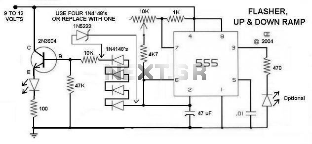
Here is a Simple Circuit to give a Flashing LED, With a "Rising and Falling" Brightness. It Uses the Sawtooth waveform from pins 2 and 6 to create the rise and fall. The Resistor and LED on Pin 3...
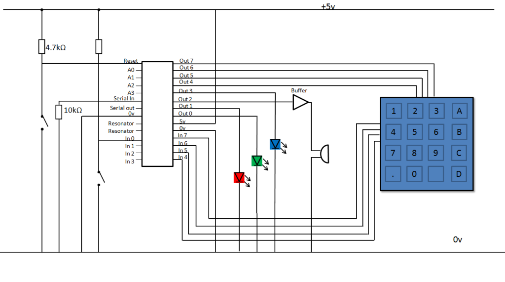
A keypad lock is being developed using a PIC microcontroller and a passive keypad with 8 pins, consisting of 4 input and 4 output pins. Each input pin corresponds to a row of numbers on a 4x4 keypad, while...
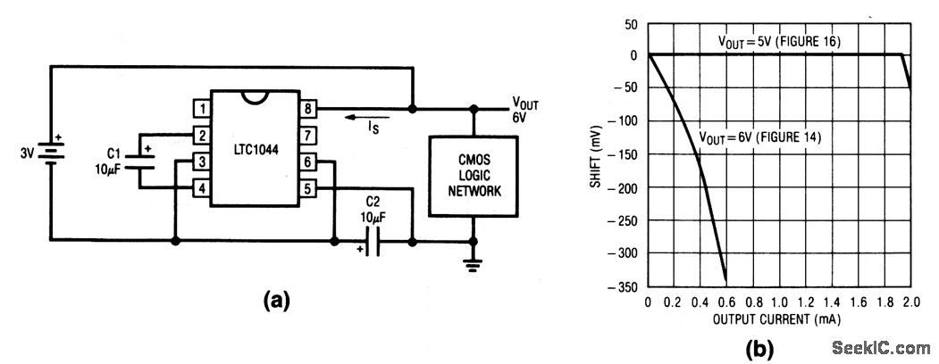
This circuit doubles the available battery voltage using an LTC1044 switched-capacitor voltage converter. It is designed to power low-power 74-CMOS (3 to 15 V) equipment for extended periods from two small 1.5 V cells. The efficiency exceeds 90% for...