
Car Headlights Timer Circuit Schematic
The timer circuit operates on a straightforward principle utilizing a capacitor, resistors, and transistors to control the relay that activates the headlights. Initially, when the button P1 is pressed, capacitor C1 begins to charge from the 12V supply of the vehicle's battery. The charging process allows Q1, a switching transistor, to enter saturation, which in turn drives Q2, another transistor that controls the relay RL1. This relay, when energized, connects the vehicle's headlights to the power supply, allowing them to remain illuminated.
The timing mechanism relies on the RC (resistor-capacitor) time constant, where the product of R1 and C1 determines the duration for which the headlights will stay on. The voltage across C1 decreases as it discharges through R1, and once it drops below 0.7V, Q1 turns off, deactivating Q2 and consequently the relay RL1, which turns off the headlights.
In the alternative configuration using the interior lamp, the circuit becomes even more user-friendly. The diode 1N4002 ensures that the capacitor charges only when the door is open. When the door closes, the discharge path is established, allowing the circuit to function without manual intervention. This modification enhances the convenience of the timer, making it a practical addition to any vehicle for improved safety and ease of use in dark environments. Proper selection of component values is crucial to achieving the desired timing interval and ensuring reliable operation of the circuit under various conditions.This device is a simple timer, allowing to keep on the headlights of your vehicle for about 1min. and 30sec. , e. g. when accessing some dark place, without the necessity of coming back to switch-off the lights. Pushing on P1 allows C1 charging to full 12V battery supply. Therefore Q1 is driven hard-on, driving in turn Q2 and its Relay load. The hea dlights are thus activated by means of the Relay contact wired in parallel to the vehicle`s headlights switch. RL1 remains activated until C1 is almost fully discharged, i. e. When its voltage falls below about 0. 7V. The timing delay of the circuit depends by C1 and R1 values and was set to about 1min. and 30sec. In practice, due to electrolytic capacitors wide tolerance value, this delay will vary from about 1min.
and 30sec. to 1min. and 50sec. An interesting variation is to use the inside lamp as a command source for the timer. In this way, when the door is opened C1 is charged, but it will start to discharge only when the door will be closed, substituting pushbutton operation. To enable the circuit acting in this way, simply connect the cathode of a 1N4002 diode to R1-C1 junction and the anode to the "live" lead of the inside lamp.
This lead can be singled-out using a voltmeter, as it is the lead where a 12V voltage can be measured in respect to the vehicle frame when the lamp is on. 🔗 External reference
Related Circuits
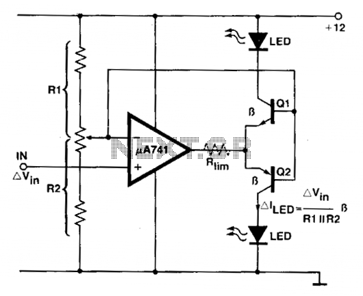
An operational amplifier (op amp) is utilized as a comparator and as a current sink for an LED. The output voltage of the amplifier varies by approximately 1.4 V based on the direction of the current. At any given...
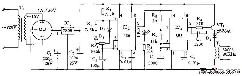
Adjust the RP1 to modify the pulse duty cycle of IC2, which in turn alters the pulse oscillation time of IC3. This regulation allows for the control of ozone generation time, effectively changing the concentration of ozone in the...
Dunlop Cry Baby Wah Wah Schematic. It is challenging to replicate the Cry Baby sound due to its unique characteristics. The Dunlop Cry Baby Wah Wah pedal is renowned for its distinctive tonal qualities and is a staple in many...
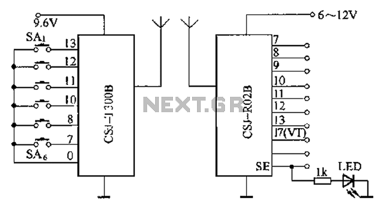
The CSJ-T300B/CSJ-R02B is an enhanced digital encoding and decoding circuit developed based on the CSJ-T300A/CSJ-R02A. It forms a remote control circuit that includes the CSJ-T300B and CSJ-R02B components, as illustrated below. The CSJ-T300B/CSJ-R02B circuit architecture is designed to facilitate improved...
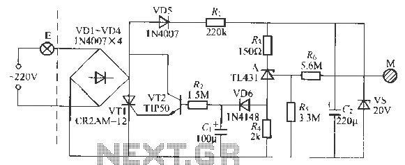
This circuit is a touch-sensitive lamp delay switch characterized by minimal static power consumption. It utilizes an external switch terminal, which can directly replace a standard switch. The circuit features a novel precision voltage regulator integrated circuit, such as...
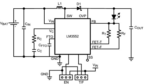
For this LED driver electronic project, a DC power supply circuit is required to provide an output voltage between 2.7V and 5.5V. The supply voltage must be applied between Vin and GND. The T/F jumper connects the T post...
Warning: include(partials/cookie-banner.php): Failed to open stream: Permission denied in /var/www/html/nextgr/view-circuit.php on line 713
Warning: include(): Failed opening 'partials/cookie-banner.php' for inclusion (include_path='.:/usr/share/php') in /var/www/html/nextgr/view-circuit.php on line 713