
Parallel Path Magnet Motor
The Parallel Path Magnet Motor (PPMM) SRSM7 version 7 represents a significant evolution in motor design, particularly through the integration of ferrite magnets. The reduction in size from a rectangular to a cylindrical magnet not only optimizes spatial efficiency but also alters the magnetic field dynamics, which can enhance performance characteristics at lower voltages. The ability to operate at a mere 1 V and 0.1 A indicates a highly efficient design that minimizes energy consumption while maintaining functional output.
The motor's nominal power rating of approximately 1 kW suggests that it is capable of handling substantial loads, making it suitable for various applications. The operational range of 0.7 V to 30 V allows for flexibility in different environments, accommodating various power supply conditions. The initial power draw of 0.15 W at startup is indicative of a low-energy requirement for activation, which is advantageous for applications where energy conservation is critical.
The design's energy recovery subsystem, which consumes 27 W, plays a crucial role in enhancing overall efficiency by reclaiming energy that would otherwise be lost during operation. This feature allows the motor to maintain a manageable power consumption of only 3 W during typical operation, highlighting its potential for sustainable energy applications.
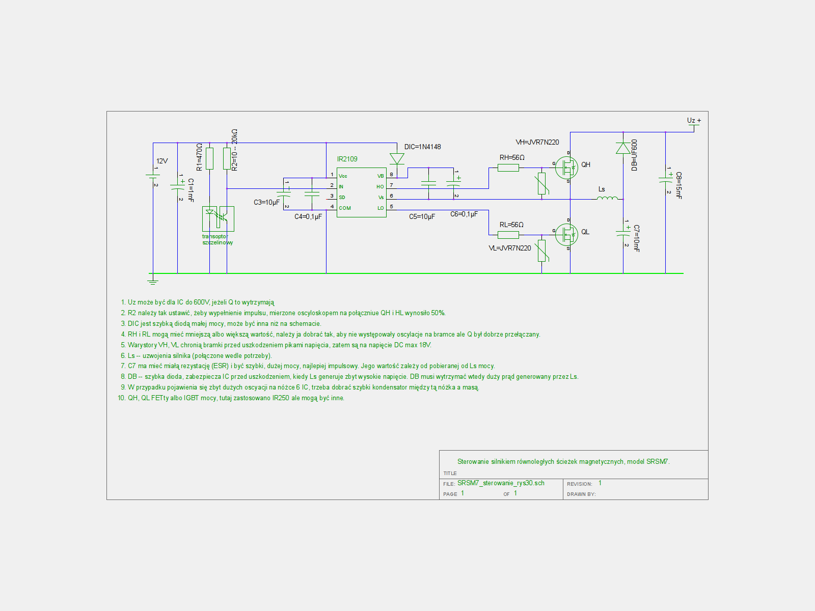
Further exploration of this technology may benefit from detailed schematics and technical documentation, which would provide insights into the specific configurations and electrical characteristics of the motor. The absence of such information in the current resources suggests an opportunity for additional research and development, particularly in optimizing the efficiency and performance of the ferrite magnets in the PPMM design. Continued investigation into the underlying principles of this motor design could lead to innovative applications and advancements in the field of electric motor technology.Before one magnet was 2x2x3 cm, now it is a round one 1. 5 x 2 cm only. This makes a huge difference, the motor can be run on1 V and 0. 1 A that makes 0. 1 W. you will find a lot of info, and cut time on your project, these two university students have done a lot of R and D on it, plus they have a new patent on it, yes a new patent but the all thing is open book, the tread is in Italian, use any of the web translator, i hope this helps you out Thank you. I did, a few weeks ago, went through the entire text with translation to English. But I didn`t find any patent file. Also I didn`t find schematic or other technical info that I can use to progress in my experiments. Maybe I missed it Continuing my research with PPMM (Parallel Path Magnet Motor) version 7. The difference is that this motor has ferrite magnets, as you suggested. They are much weaker compared to the previous ones, neodymium, but same dimensions. Parallel path magnet motor SRSM7 version 7 of nominal ~ 1 kW power - a test how it works from 0. 7 V to 30 V, when drawing power starting from 0. 15 W. This version differs from the previous ones with magnets, now ferrite magnets are used, not neodymium ones. Parallel path magnet motor version SRSM7. The input is set up so as the entire system consumes 30 W. The energy recovery subsystem consumes 27 W, so the motor itself practically is using only 3 W. 🔗 External reference
Related Circuits
A stepper motor is a motor controlled by a series of electromagnetic coils. The center shaft has a series of magnets mounted on it, and the coils surrounding the shaft are alternately energized or de-energized, creating magnetic fields that...
The control signals for the motor's rotation are generated by an 8051 microcontroller. For foundational concepts and information about a servo motor, refer to the article on Servo Motors. The source code utilized is based on the AT89S51 microcontroller....
This diagram illustrates the usage of the L200 device for controlling the speed of permanent magnet motors. By utilizing resistors R1 and R2, the desired speed can be achieved. The L200 is a versatile integrated circuit designed for various applications,...
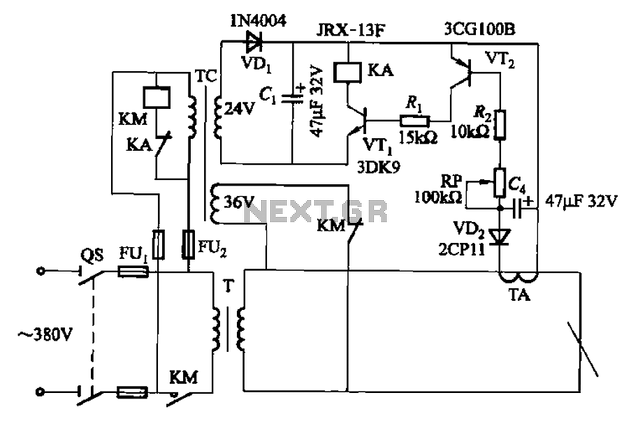
The AC arc welding machine's transistor load path for the power from the second circuit is illustrated. The figure shows a current transformer with a core cross-section of 25 mm². The transformer has a primary winding with a certain...
It is important to note that the Bedini Trifilar SG or SSG are not over-unity (OU) systems. They function as one-to-one energy shuttle systems, utilizing one charged input battery to recharge four or more output batteries. When configured correctly,...
Motorcycle battery charger power supply. Refer to the mentioned page for an explanation of the power supply related circuit diagram. The description of the battery charger indicator: The circuit above enhances the appearance of a simple battery charger, making...