
Stepper Motor circuits
Stepper motors are characterized by their ability to achieve precise control of angular position, making them suitable for applications requiring accurate movement. The unipolar stepper motor's configuration, with its center-tapped coils, allows for simpler drive circuitry, while the bipolar stepper motor configuration, lacking a center tap, offers greater torque and efficiency. The implementation of H-bridges for bipolar stepper control enables the reversal of current direction, which is crucial for achieving bidirectional movement.
For applications requiring interfacing with microcontrollers, it is essential to ensure that the chosen components, such as the Darlington Transistor Array or H-bridge, are compatible with the logic levels of the microcontroller being used. Additionally, the power supply must be appropriately rated to handle the current demands of the stepper motor, as exceeding the rated voltage or current can lead to overheating or damage.
In summary, stepper motors are versatile components in the field of electronics, offering precise control over motion through a well-defined stepping sequence. Their application spans a wide range of industries, from robotics to printing, where accurate positioning is critical. Understanding the differences between unipolar and bipolar configurations, as well as the driving methods, is vital for successful integration into electronic systems.A stepper motor is a motor controlled by a series of electromagnetic coils. The center shaft has a series of magnets mounted on it, and the coils surrounding the shaft are alternately given current or not, creating magnetic fields which repulse or attract the magnets on the shaft, causing the motor to rotate. This design allows for very precise co ntrol of the motor: by proper pulsing, it can be turned in very accurate steps of set degree increments (for example, two-degree increments, half-degree increments, etc. ). They are used in printers, disk drives, and other devices where precise positioning of the motor is necessary.
The unipolar stepper motor has five or six wires and four coils (actually two coils divided by center connections on each coil). The center connections of the coils are tied together and used as the power connection. They are called unipolar steppers because power always comes in on this one pole. The bipolar stepper motor usually has four wires coming out of it. Unlike unipolar steppers, bipolar steppers have no common center connection. They have two independent sets of coils instead. You can distinguish them from unipolar steppers by measuring the resistance between the wires. You should find two pairs of wires with equal resistance. If you`ve got the leads of your meter connected to two wires that are not connected (i. e. not attached to the same coil), you should see infinite resistance (or no continuity). Like other motors, stepper motors require more power than a microcontroller can give them, so you`ll need a separate power supply for it.
Ideally you`ll know the voltage from the manufacturer, but if not, get a variable DC power supply, apply the minimum voltage (hopefully 3V or so), apply voltage across two wires of a coil (e. g. 1 to 2 or 3 to 4) and slowly raise the voltage until the motor is difficult to turn. It is possible to damage a motor this way, so don`t go too far. Typical voltages for a stepper might be 5V, 9V, 12V, 24V. Higher than 24V is less common for small steppers, and frankly, above that level it`s best not to guess.
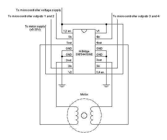
To control a unipolar stepper, you use a Darlington Transistor Array. The stepping sequence is as shown above. Wires 5 and 6 are wired to the supply voltage. To control a bipolar stepper motor, you give the coils current using to the same steps as for a unipolar stepper motor. However, instead of using four coils, you use the both poles of the two coils, and reverse the polarity of the current.
The easiest way to reverse the polarity in the coils is to use a pair of H-bridges. The L293D dual H-bridge has two H-bridges in the chip, so it will work nicely for this purpose. Knowing the position is a matter of knowing how many degrees per step, and counting the steps and multiplying by that many degrees. So for examples, if you have a 1. 8-degree stepper, and it`s turned 200 steps, then it`s turned 1. 8 x 200 degrees, or 360 degrees, or one full revolution. In every step of the sequence, two wires are always set to opposite polarities. Because of this, it`s possible to control steppers with only two wires instead of four, with a slightly more complex circuit.
The stepping sequence is the same as it is for the two middle wires of the sequence above: Because both unipolar and bipolar stepper motors are controlled by the same stepping sequence, we can use the same microcontroller code to control either one. In the code examples below, connect either the Darlington transistor array (for unipolar steppers) or the dual H-bridge (for bipolar steppers) to the pins of your microcontroller as described in each example.
There is a switch attached to the microcontroller as well. When the switch is high, the motor turns one direction. When it`s low, it turns the other direction. Wire pins 9-12 of the BX-24 to inputs 1-4 of the Darlington transistor array, respectively. If you`re using the PicBasic Pro code, it`s designed 🔗 External reference
Related Circuits
Camping today often requires bringing various electronic devices for daily activities or entertainment. Frequently, a charge is needed for these devices. In modern camping scenarios, the reliance on electronic devices has significantly increased. Campers typically bring smartphones, tablets, GPS devices,...
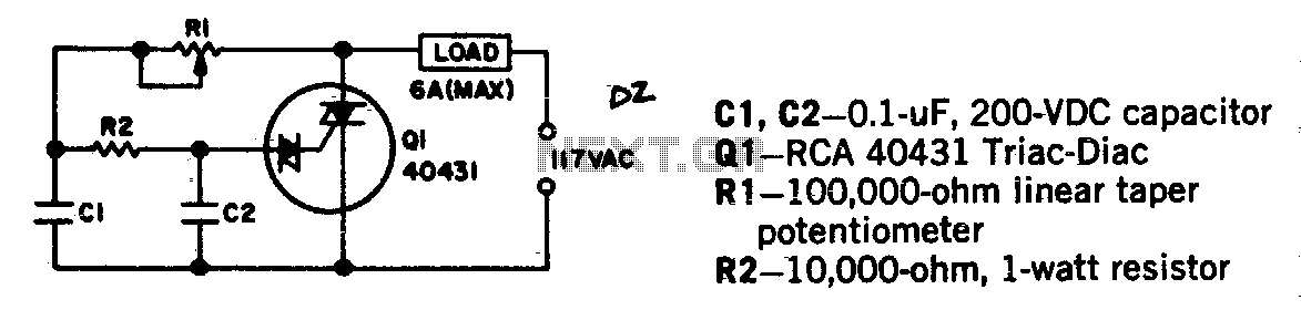
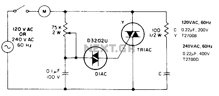
Universal motors and shaded-pole induction motors can be effectively controlled using a full-wave Triac speed controller. Component Q1 integrates both the Triac and diac trigger diodes within a single package. The motor employed for the load should not exceed...
A schematic arrangement for a two-quadrant controller is shown in the figure below. This figure illustrates the outer speed control loop and the inner current control loop. The tachogenerator derives the speed feedback signal; alternatively, an approximation of the...
This single time-constant circuit can be utilized for proportional speed control of induction motors, such as shaded pole or permanent split-capacitor motors, when the load remains constant. The circuit is particularly well-suited for applications that necessitate speed control within...
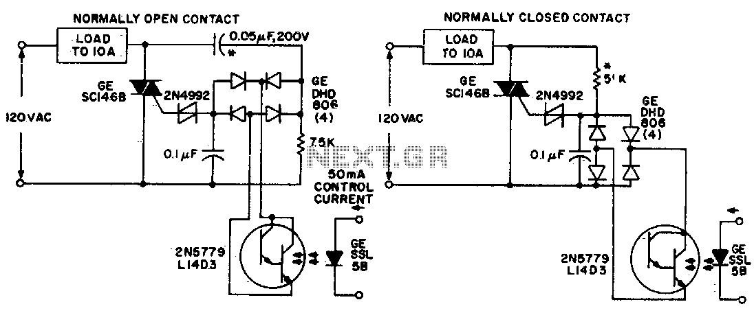
Both circuits utilize the GE SC146B, a 200 V, 10 A Triac for load current contacts. These triacs are activated by standard SBS (2N4992) trigger circuits, which are managed by a photo-Darlington configuration, functioning through the DA806 bridge as...
The challenge is to control the speed of the motor. One approach is to use a plane, radio, and speed control integrated with the motor, but this is not ideal. Alternatively, mounting the motor on a bench and directly...
Warning: include(partials/cookie-banner.php): Failed to open stream: Permission denied in /var/www/html/nextgr/view-circuit.php on line 713
Warning: include(): Failed opening 'partials/cookie-banner.php' for inclusion (include_path='.:/usr/share/php') in /var/www/html/nextgr/view-circuit.php on line 713