
Parallel Port CW Interface for N3FJP

The described circuit integrates a K2 transceiver with a ThinkPad laptop for CW contesting purposes, utilizing both a serial port for rig control and a parallel port for keying functionality. The design aims to maintain signal integrity by segregating keying from the serial communication line, addressing concerns regarding the susceptibility of parallel ports to RF interference.
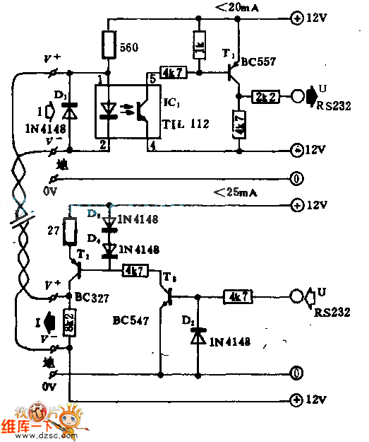
The core of the interface involves an opto-coupler, which serves to isolate the computer's parallel port from the K2, ensuring that the keying signal is clean and free from potential noise. The choice of a 1N5817 Schottky diode in the keying line is particularly significant, as these diodes are known for their low forward voltage drop and fast switching capabilities, making them suitable for high-speed applications like CW transmission.
The use of a potentiometer for fine-tuning the current through the opto-coupler's LED is a practical solution to accommodate variations in the output of the ThinkPad's parallel port. This adjustability allows for optimization of the keying signal, ensuring reliable operation without compromising the performance of the K2's autodetect feature. Eventually, transitioning to a fixed resistor will enhance the circuit's stability and reliability, reducing the risk of inadvertent adjustments that could lead to performance inconsistencies.
In summary, this circuit design not only meets the immediate requirements for CW contesting but also reflects a thoughtful approach to interfacing vintage and modern technology while maintaining signal integrity and performance reliability. The careful selection of components and the iterative process of tuning the circuit exemplify best practices in electronic design for amateur radio applications.I`ve been doing some CW contesting with my K2 and N3FJP`s Logging Software and since I now have this modern rig with computer control and everything I wanted to connect it up to my old Thinkpad and use the serial port for rig control and the parallel port for keying. Now, I`ve heard talk that you can run both rig control and keying off the same serial port and I`ve also heard that the parallel port is a crummy, RF-sensitive interface, but I really want to keep my K2 serial line "pure" and do the keying on a separate circuit. (In practice, the final circuit has worked fine and I haven`t had any RF problems. ) N3FJP`s web site had a serial schematic, and he has since added a transistor driven parallel schematic, but I looked all over the web for an opto-coupled, parallel port circuit and couldn`t find one, so after I finally built my own interface I decided to make this page and maybe save someone else some time.
I bought a stereo headphone cable extension cable at Radio Shack and cut it, then mounted the interface components in a 25 pin D-shell. The final product looks like this: The schematic looks like this (it was easier to just draw it on paper and scan it than fiddle with a drawing program, so please excuse the somewhat rough quality.
) I did a lot of math to figure out the right value for the current limiting resistor that is in the line that drives the LED in the opto-coupler. I even got a lot of help from the Elecraft Reflector, in particular Dale, KK6RK was very patient over several e-mails and figured a 390 ohm resistor would provide the needed 8-9ma to the LED.
But, in the end, it was very hard to figure out how much current my crazy Thinkpad parallel port could source and nothing seemed to work. That`s when I became a complete hack and dropped a 1K ohm pot into the circuit and twiddled it while sending from the computer until things started working.
I discovered I could start to get reliable keying around 130 ohms and 100 ohms worked well. I think this is a good way to get a workable value for a particular situation and I recommend it - though I do intend to swap out the pot for a- - fixed value resistor since the pot is "twitchy" and can be bumped out of value easily. The 1N5817 diodes in the keyline that activate the K2`s autodetect keying circuit work very well and I`ve seen some traffic on the Elecraft reflector that indicate these Schottky Rectifier diodes have good timing characteristics for this application (they turn on together and don`t confuse the K2).
MERCHANDISE: STOCK NUMBER ORDERED AVAILABILITY PRICE Ext. Price = 78-4N35 1 1 Ships Immediately 0. 290 0. 290 583-1N5817 2 2 Ships Immediately 0. 280 0. 560 🔗 External reference
Related Circuits
This circuitry facilitates the connection between the computer's Z RS-23 serial interface and the current ring circuitry. It converts the voltage signal of the transmission into a current signal of 20 mA, achieving a maximum speed of 1200 bits....
The entire AVR programmer has been built using common parts and fits in the case of the serial connector. The socket PCB has been created to accommodate a 28-DIP AVR ATmega8 microcontroller, but a socket PCB can be designed...

The 2x16 Parallel LCD is an 8-bit or 4-bit parallel interfaced LCD. This unit allows the user to display text, numerical data, and custom-created characters. The LCD utilizes the HD44780 series LCD driver from Hitachi or an equivalent controller....

This circuit is designed for interfacing phone projects with the telephone line. It includes a ringer, has the capability to interrupt the wiring, and provides isolation for the project from the phone line. The circuit operates by integrating a ringer...

Below are three examples of controlling a relay from the PC's parallel printer port (LPT1 or LPT2). Figure A shows a solid-state relay controlled by one of the parallel port data lines (D0-D7) using a 300-ohm resistor and a...

The TS4962 is a differential class-D BTL power amplifier capable of driving up to 2.2W into a 4-ohm load and 1.4W into an 8-ohm load at 5V. It achieves outstanding efficiency (typical 88%) compared to standard AB-class audio amplifiers....