
Parallel Port Relay Interface Circuit
The described circuit utilizes the parallel printer port of a PC to control relays, showcasing both solid-state and mechanical relay configurations. In the solid-state relay setup, a 300-ohm resistor is employed to limit the current flowing from the data line of the parallel port, ensuring safe operation of the relay. The solid-state relay is activated when a logic low ("0") is sent to the data line, providing a fast switching capability suitable for applications requiring rapid on/off control.
For the mechanical relays illustrated in Figures B and C, the use of transistors serves as an interface between the low-voltage logic levels of the parallel port and the higher current requirements of the relays. In Figure B, the transistor is configured such that writing a logic high ("1") to the data line allows current to flow through the relay coil, energizing it and closing the associated switch. Conversely, in Figure C, the transistor is configured to energize the relay when a logic low ("0") is written, demonstrating flexibility in controlling relay states based on the desired logic.
The common connection from the power supply's negative terminal to the ground pins of the parallel port ensures a stable reference point for all components involved in the circuit. The use of 5-volt logic levels is standard in many digital circuits, and the option to utilize a series of batteries to achieve this voltage illustrates a practical approach for portable applications.
The program written in QBasic facilitates interaction with the circuit, allowing the user to monitor the state of the input lines corresponding to the switches. The logic of the program is simple yet effective: it reads the state of the switches and converts that information into a single byte, allowing easy interpretation of which switches are active. The use of inverted logic for certain pins adds complexity but also flexibility in design, accommodating various input configurations.
Overall, this circuit design exemplifies an effective method for interfacing a PC with external devices, such as relays, using the parallel printer port. It highlights the versatility of parallel ports in controlling various electronic components, making it a valuable technique for hobbyists and professionals alike.Below are three examples of controlling a relay from the PC`s parallel printer port (LPT1 or LPT2). Figure A shows a solid state relay controlled by one of the parallel port data lines (D0-D7) using a 300 ohm resistor and 5 volt power source. The solid state relay will energize when a "0" is written to the data line. Figure B and C show mechanical relays controlled by two transistors. The relay in figure B is energized when a "1" is written to the data line and the relay in figure C is energized by writing a "0" to the line. In each of the three circuits, a common connection is made from the negative side of the power supply to one of the port ground pins (18-25).
There are three possible base addresses for the parallel port You may need to try all three base addresses to determine the correct address for the port you are using but LPT1 is usually at Hex 0378. The QBasic "OUT" command can be used to send data to the port. OUT, &H0378, 0 sets D0-D7 low and OUT, &H378, 255 sets D0-D7 high. The parallel port also provides four control lines (C0, C1, C2, C3) that can be set high or low by writing data to the base address+2 so if the base address is Hex 0378 then the address of the control latch would be Hex 037A.
Note that three of the control bits are inverted so writing a "0" to the control latch will set C0, C1, C3 high and C2 low. The diagram below shows 5 switches connected to the 5 input lines of the parallel port. An external 5 volt power supply is used to provide high logic levels to the input pins when the switches are open.
Three 1. 5 volt batteries in series can be used to obtain 4. 5 volts which is close enough. The 330 ohm resistors in series with the port connections provide some protection in case a connection is made to the wrong pin. If you are sure of the connections, the 330 ohm resistors can be left out and the switches connected directly to the input pins.
The negative side of the power supply should be connected to the ground point, or any pin from 18 to 25. The following short QBasic program can be used to read the state of the switches. QBASIC. EXE can be found in the "OLDMSDOS" directory of the Windows 95/98 CD Rom. Note that there are three possible printer port address that correspond to LPT1, LPT2 and LPT3 and LPT1 is usually the one to use which is at address decimal 889.
The program waits for the user to press the enter key before reading the state of the 5 input lines. The state of the 5 lines is received as a single 8 bit number between 0-255 which is stored as the value of (V). Each switch input represents a decimal value of 8, 16, 32, 64 and 128 which correspond to pins 15, 13, 12, 10 and 11.
The last 3 bits (1, 2 and 4) are not used and should return a high level, so the value received with all switches open should be 1+2+4+8+16+32+64=127. If a switch is closed and the input is at ground, the value will be 0 except for pin 11 which is inverted and yields a value of 128 and 0 when high, so the value received when all switches are closed should be 1+2+4+128=135.
🔗 External reference
Related Circuits
1. Abstract Wet-garden is an interactive flower garden and an ambient indoor sculpture. When people walk around it, it changes motion and LED blinking speed. Wet-design is designed for everyone who wants a tangible interaction object and an interesting...
For a robot to perform its assigned tasks, a controller is necessary. This controller may be mechanical, electrical, electronic, or a combination of these. It acts as the brain of the entire system, providing the robot with its intelligence....

A circuit breaker is an automatically operated electrical switch designed to protect an electrical circuit from damage caused by overload or short circuit. Its basic function is to detect a fault condition and, by interrupting continuity, immediately discontinue electrical...
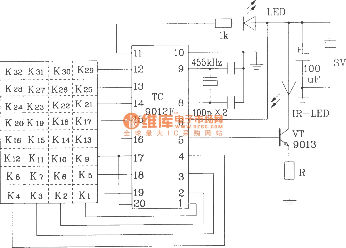
The TC9012 is a specialized off-screen remote control code transmitter. It incorporates an oscillator, divider timing generator, system code latch, data storage, key scan input, key scan output, and carrier control and output units. The internal 8-bit system code...
Almost all 24V power systems in trucks, 4WDs, RVs, boats, etc., utilize two series-connected 12V lead-acid batteries. The charging system can only sustain the total voltage of the individual batteries. If one battery is failing, this circuit will illuminate...
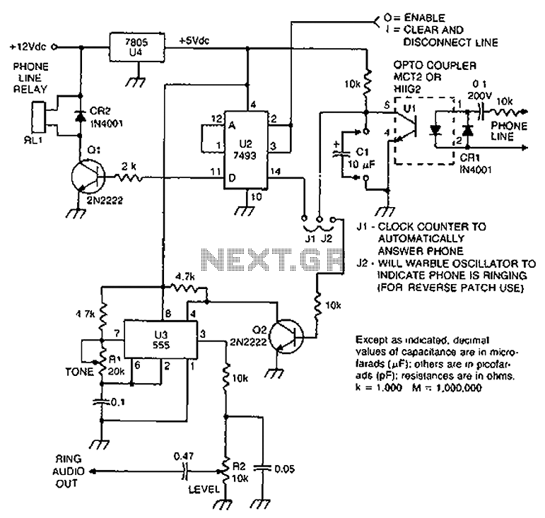
Check the loop circuit for an automatic telephone answering system or a tone generator for use in reverse automatic repair. The loop circuit in an automatic telephone answering system is designed to detect incoming calls and activate the answering mechanism....