
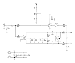
Passive Summing Schematic

The 16-channel passive summing mixer is designed to combine multiple audio signals into a single output while maintaining the integrity of the original audio quality. The schematic typically consists of multiple input channels, each equipped with resistors that facilitate the summing process. The resistors are strategically selected to ensure that each input signal is attenuated appropriately, preventing any single channel from dominating the mix.
In a standard configuration, each input channel will feature a resistor connected to the audio signal path, followed by a common output bus where all signals converge. The choice of resistor values is crucial; they should be selected to achieve a balanced mix without introducing significant noise or distortion. Common resistor values for such applications range from 1kΩ to 10kΩ, depending on the desired input impedance and overall mixer design.
The output of the mixer is typically connected to a buffered amplifier stage to drive the final output signal, ensuring that the combined signal maintains its strength and fidelity. This buffer stage can be implemented using an operational amplifier configured in a non-inverting mode, which provides high input impedance and low output impedance, allowing for better compatibility with subsequent audio equipment.
In addition to the basic summing function, considerations for grounding and shielding are essential to minimize hum and interference. A star grounding scheme is often recommended, where all ground connections converge at a single point to reduce ground loops.
Overall, this passive summing mixer design is ideal for applications where simplicity, low cost, and minimal signal coloration are desired, making it a popular choice among audio engineers and hobbyists alike.So I`ve searched the forums, and the internet, and I`ve put together a schematic for a 16 channel passive summing mixer I would like to build. I`m.. 🔗 External reference
Related Circuits
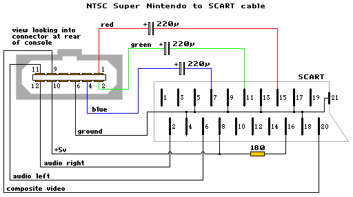
The schematic diagram is similar to the SNES NTSC RGB cable, with the only modification being the addition of capacitors to the RGB line. The diagram is accurate, but it does not include capacitors. A GameCube SCART lead can...
All modern infrared (IR) remote control devices generate a continuous coded stream of pulses at 37.9 kHz when any button on the device is pressed. These IR pulses are received and decoded by a compatible device, such as a...
Electronic Project EPROM Emulator. This EPROM Emulator was designed to complement the EPROM Programmer (Mark 2). The EPROM Emulator serves as a versatile tool for testing and developing electronic circuits that utilize EPROM (Erasable Programmable Read-Only Memory) chips. This device...
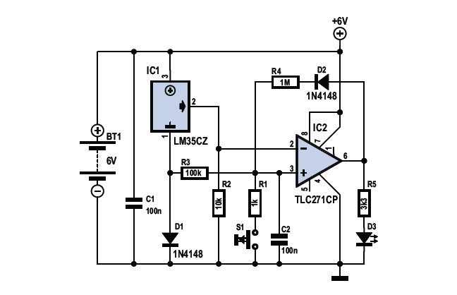
To determine whether it is freezing, one needs to measure the temperature accurately. This requires a reliable temperature sensor. The LM35CZ sensor, which operates within a range of -40 to 110 °C, is suitable for this purpose. It is...
This application note provides valuable PC board layout, bypassing, and decoupling guidelines for customers who are implementing high-speed data converters in their designs. High-speed data converters are critical components in modern electronic systems, requiring careful consideration of their integration into...
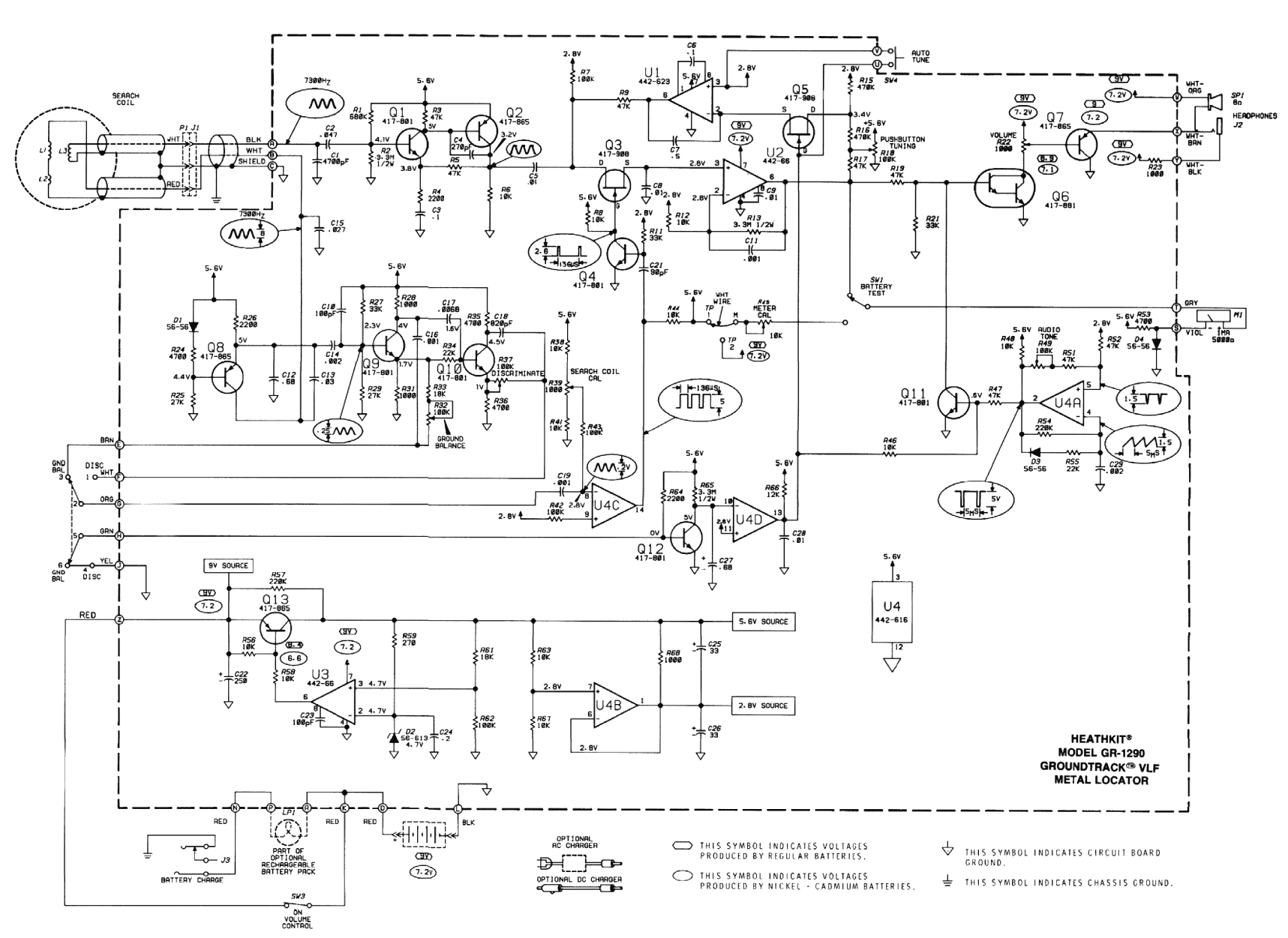
The original coil that came with the Heathkit project was preassembled at the factory. It had a diameter of around 15 cm (6 inches). A larger (30 cm, 12 inches) coil can be made using the following data. The design...