
PC-Based Data Logger circuit description with PCB layout
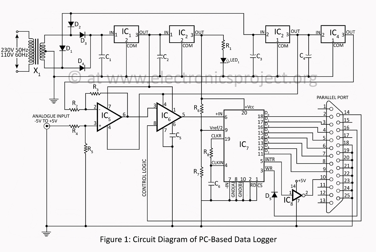
The PC-based data logger serves as an essential tool in physics laboratories, enabling the automation of experiments and the monitoring of various physical variables. This device interfaces with a computer to collect data from sensors, which may include temperature, pressure, voltage, and other measurable parameters. The data logger typically features multiple input channels, allowing for the simultaneous monitoring of several variables.
The system architecture usually consists of a microcontroller or dedicated data acquisition hardware that interfaces with the sensors. The data acquisition system converts the analog signals from the sensors into digital data that can be processed by the computer. The software component of the data logger provides a user-friendly interface for configuring experiments, visualizing data in real-time, and storing data for later analysis.
In addition to logging data, the software often includes capabilities for data analysis, allowing users to generate graphs, perform calculations, and export results in various formats. This functionality is crucial for educational purposes, as it aids in the understanding of physical principles through hands-on experimentation.
Furthermore, the design of the data logger may incorporate features such as wireless communication for remote monitoring, data encryption for security, and power management systems to ensure long-term operation during experiments. Overall, the PC-based data logger is a versatile and valuable instrument in the study of physics, enhancing both teaching and research capabilities.PC-based data logger used in physics laboratories for automating simple experiment and or monitoring slowly varying physical variable various pc-based project . 🔗 External reference
Related Circuits
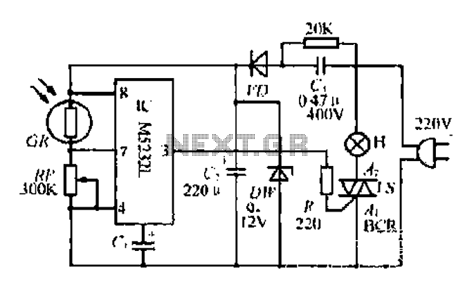
The DW L11 capacitor steps down voltage into the Jenru half crossing according to Yin electrical specifications. After receiving power at the bin CI SH output terminal, it regulates the voltage to liVI/r j, ensuring a right cut in...
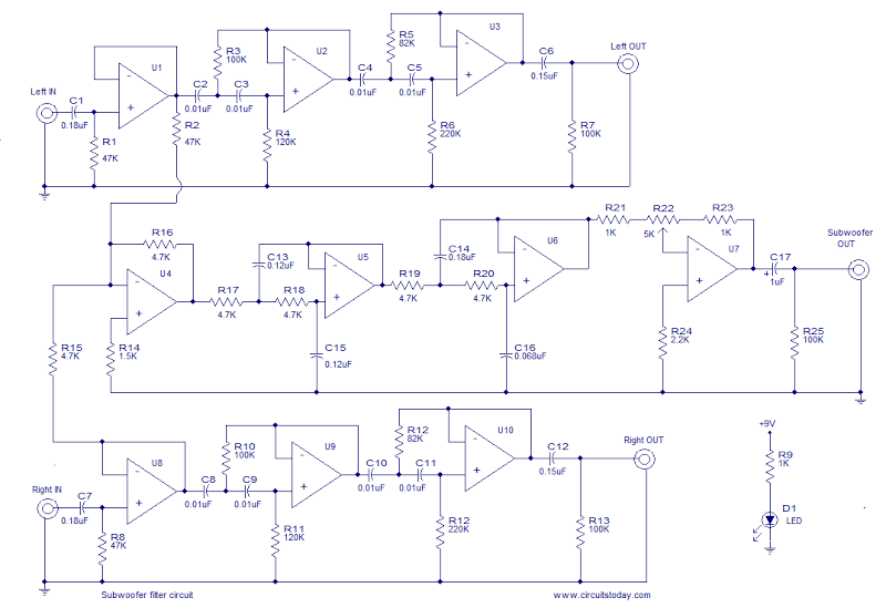
This is the schematic diagram of an operational amplifier (op-amp) based subwoofer filter. Audio frequencies below 200 Hz are typically categorized within the subwoofer range, indicating that a subwoofer filter should have a cutoff frequency around 200 Hz. The...
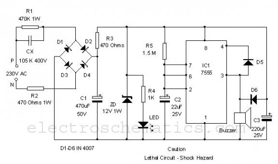
This is a simple power resumption alarm circuit that can be installed within the switch box. It emits beeping sounds when power is restored following a power outage. The power resumption alarm circuit serves as a practical solution for alerting...
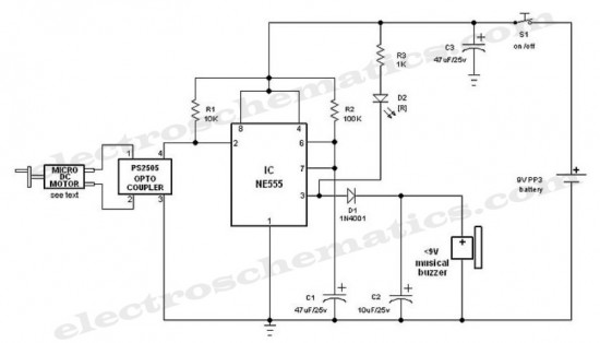
This is an interesting hobby circuit for a crank doorbell. The circuit is built around a 555 timer and a musical piezo buzzer, powered by a 9-volt battery. A single 9-volt PP3/6F22 compact battery is sufficient to power the...
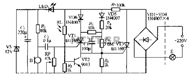
A relatively simple circuit for controlling a stair walkway light with a delay feature. The circuit has a drawback in that the voice activation is somewhat less sensitive, making it sometimes difficult to trigger with general conversation. However, it...
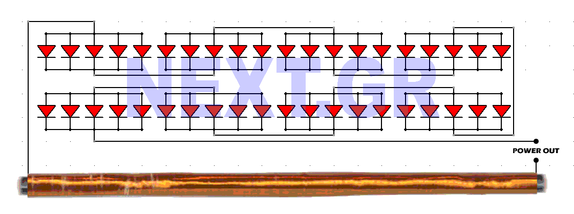
This schematic converts surrounding radio waves into usable electrical current. The power levels can be increased by incorporating additional diodes. The key factors in this device are the type of diodes used and the construction of the antenna. The...