
Free Power Generator Circuit
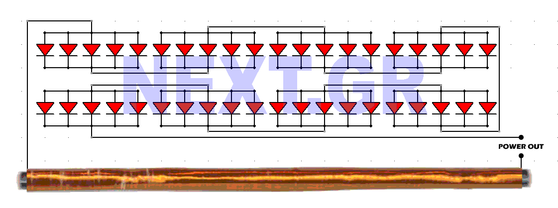
The antenna design is crucial for optimal performance. It should be constructed using a ferrite core. An 18-foot length of wire should be coiled around the largest ferrite rod available. Multiple ferrite rods can be glued together to achieve the necessary antenna length, with an ideal target being 30 inches or more.
For the diodes, it is recommended to use low-loss germanium diodes with a low breakdown junction voltage, approximately between 0.2 to 0.4 volts. In environments with significant radio frequency interference, each diode may produce around 30 mV. Further details and testing results will be provided in the future.
The described circuit utilizes a simple yet effective method of energy harvesting from ambient radio waves. The antenna, acting as the primary receiver, captures electromagnetic energy from the environment. The choice of a ferrite rod for the antenna enhances the reception due to its magnetic properties, which improve the inductance and efficiency of the antenna design.
The wire length of 18 feet is strategically chosen to resonate at various frequencies typically found in the radio spectrum, allowing the antenna to capture a wider range of signals. The construction of the antenna can be adjusted by adding more ferrite rods, thereby increasing the effective length and improving the overall gain of the system.
Diodes play a critical role in rectifying the alternating current (AC) signals received by the antenna into direct current (DC). The selection of germanium diodes is important due to their low forward voltage drop, which maximizes the efficiency of power conversion. The low breakdown voltage further allows the circuit to operate effectively even under low signal conditions, which is often encountered in urban areas with high levels of radio frequency noise.
The output voltage from the diode rectifiers is dependent on the number of diodes in series, as each diode contributes to the total voltage drop. Therefore, a careful balance must be struck between the number of diodes and the expected output voltage, particularly in environments with varying signal strengths.
Overall, this circuit design presents a viable solution for energy harvesting from ambient radio waves, making it suitable for low-power applications where conventional power sources are impractical. Further experimentation and refinement of the schematic will enhance performance and reliability.You need free power? This schematic transforms the surrounding radio waves to usable current. The levels of power can be stepped up by using more diodes. The critical points in this device are first the type of diodes and second the antenna construction. The more diodes the more power out! And guess what, no ground needed.. Lets begin with the antenna first. It has to be an Ferrite antenna Get a wire 18 feet long and wrap it around the the largest ferrite rod you can find! You can put many ferrite rods glued to make the length of the antenna you need. A 30 inch or more antenna, would be ideal. As for the diodes, try to find the lowest loss Germanium diodes, with the lowest breakdown junction voltage ~ 0.2 - 0.4 Volts.
Keep in mind that in a heavy radio polluted area each diode will put out about 30mV. More details and testings results comming soon.. 🔗 External reference
Related Circuits
The 7208 seven-stage decimal counter can be utilized as a frequency counter. It features latch and multiplexing functions, along with direct digital driving circuitry and display driving circuitry. The output frequency of the 7207 IC 6.5536 MHz crystal oscillator...
Since then, NL has evolved into the Microsoft Windows®-based NL4, which has been extensively used by world-class engineers in various fields of electronics for almost 10 years. NL5 is the first version to be publicly available. Unlike conventional SPICE-based...
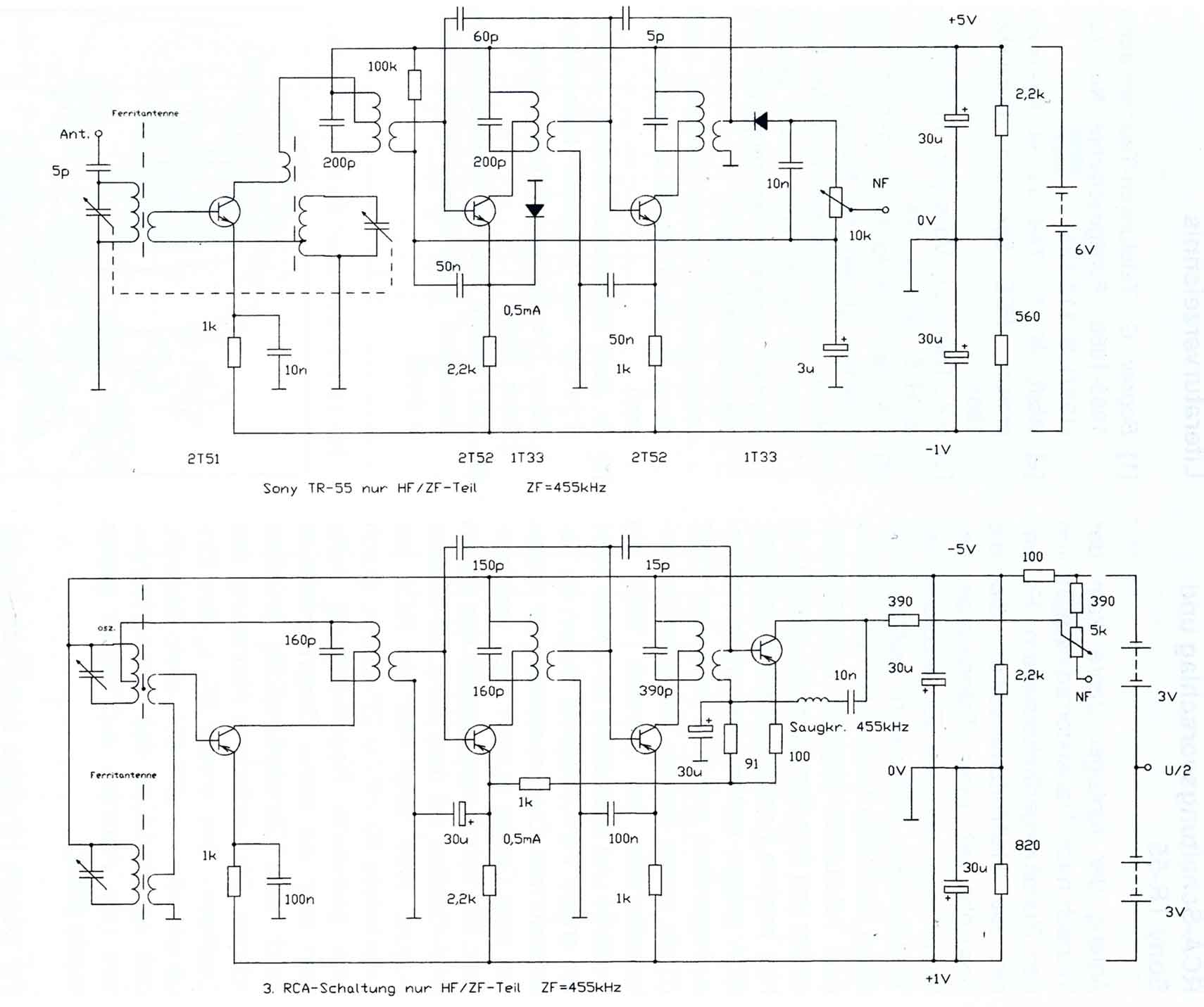
The circuitry of the Regency exhibits several unique characteristics. Notable features include the self-oscillating mixer stage, the base bias voltage of the second IF stage derived from the AF power stage, an unusual IF frequency of 262 kHz, and...
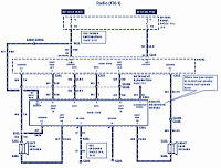
The section of the 1996 Ford Windstar wiring diagram includes details on power distribution, common connections, rear circuits, ignition systems, the fuse panel, battery connections, instrument illumination, radio wiring, left rear speaker connections, remote headphone module, solid-state components, and...
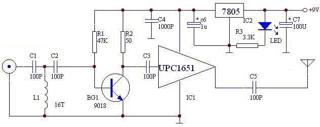
The UPC1651 FM monolithic circuit can be utilized to design a simple, low-cost FM transmitter electronic project. This circuit is specifically designed as a wideband amplifier that covers the HF band through the UHF band. Audio signals from the...
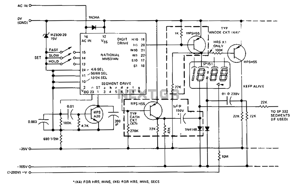
A CMOS clock circuit is capable of driving a multi-digit gas discharge display. This simple circuit does not include an alarm feature but allows for a flashing colon to indicate morning and afternoon. The circuit requires seven drive circuits...