
PC Case USB LCD

The LCD module project serves as a practical example of integrating USB HID technology with microcontroller applications, showcasing the versatility of the PIC18F2550 in managing user interfaces. The use of a 20 MHz resonator ensures reliable operation and responsiveness in communication between the host and the LCD. The choice of the ATM1602B 2x16 LCD module is significant due to its compact size, making it ideal for limited spaces within PC cases. The design approach emphasizes simplicity and accessibility, enabling users to replicate the project with minimal resources.
The hardware configuration allows for easy assembly, with the option to utilize SMD components for a more streamlined design. The incorporation of a mini-USB connector not only enhances the aesthetic appeal but also optimizes the overall footprint of the module. The soldering process for connecting the LCD to the controller board is straightforward, ensuring that even those with basic soldering skills can successfully complete the assembly.
The firmware's ability to handle raw byte commands opens up opportunities for advanced customization, enabling users to create unique display features without needing extensive programming knowledge. The host software's implementation of performance monitoring provides valuable insights into system resource usage, which can be crucial for applications requiring efficiency.
In summary, this project exemplifies the integration of microcontroller technology with user interface design, providing a functional and aesthetically pleasing solution for displaying system information in a compact form factor. The documentation and resources provided facilitate ease of replication and customization, making this project a valuable addition to the toolkit of electronics enthusiasts and developers.For the first version of my Open Source Framework for USB Generic HID devices based on the PIC18F and Windows I made a quick example of how to use the library using a USB interface for an LCD. Now that I`ve completed the second version of the library I thought it would be fun to enhance the LCD project into a completely self-contained LCD module w
hich would fit in a 5. 25 inch drive-bay of a PC case. This project explains how the LCD module can be built along with PIC firmware and Windows host software written around the C# USB Generic HID library. For the example host code the CPU and memory utilisation is displayed on the LCD along with the current time.
The hardware is the same size as the LCD itself and can be mounted directly behind the ATM1602B 2*16 LCD module to provide a compact host-powered LCD for many applications. The hardware design is extremely simple and can be built using the supplied PCB artwork or on a stripboard/breadboard.
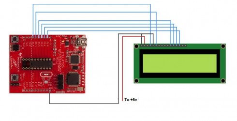
The circuit consists of a PIC18F2550 with a 20 Mhz resonator and the required components for the LCD screen and the USB. The circuit board uses mainly SMD devices (although you could fit through-hole devices in the same space it saves a lot of time drilling holes).
Also the USB connection is provided via a SMD mini-USB connector which keeps the whole module very thin and space-efficient. Only the top copper layer is used (and there are no jump wires required) so this can be easily made with a single sided PCB.
Here is a picture of the completed board: As you can see in the picture, the display is connected to the controller board using single strand wire. You simply solder the wire to the controller board then mount the LCD on top using some screws (and I used some M6 bolts to act as spacers) and then solder the wires to the LCD.
The contrast control potentiometer is mounted underneath the board to allow easy adjustment after the LCD screen has been mounted. The diode can be soldered on the top or bottom of the board; I decided to keep it on the top to make the finished module look neater.
The firmware is based on the software available from my Open Source Framework for USB Generic HID devices based on the PIC18F and Windows (Version 2_0_0_0) and implements several USB commands allowing the host to clear the display, move the cursor, output text and write a `raw` byte to the LCD display. The raw byte command allows the host to be able to send custom commands to the LCD so that you can implement things like special LCD characters without having to alter the PIC firmware (if you know a bit about the communication that is possible with the ATM1602B).
Furthermore there is no reason why you could not use the same firmware to communicate with the larger versions such as the 4*16 display. I chose the 2*16 because it can fit behind a single drive-bay cover. The host software implements the performance counters and passes the appropriate text strings to the PIC firmware.
The mechanism is very simple and should be extremely flexible if you wish to implement your own display information. In addition, version 2 of the USB HID library implements an example debugging log stream from the USB firmware to the host which is demonstrated in the host code.
As you can see from the screenshot the application monitors both the CPU and the memory usage using windows` built in performance counters. In addition there is a debug text box which shows the live streaming debug information coming from the USB firmware (which is extremely useful for more complex firmware design and debugging).
Along with the PCB artwork and the schematics is a cut-sheet which acts a template for cutting a standard 5. 25 drive-bay cover so you can mount the display in a PC Case. Here is a picture of the display mounted in my PC: PCB and Schematic - The PCB artwork and schematics in expressSCH and expressPCB format (these are freely available programs) - also includes a panel
🔗 External reference
Related Circuits
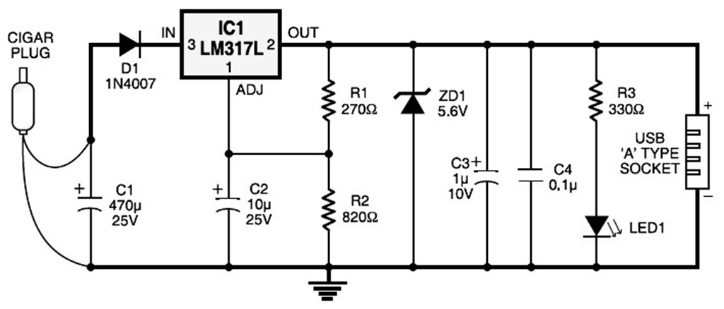
A USB port is capable of supplying more than 100 mA of continuous electric current at 5V to peripherals connected to the bus. This feature allows a USB port to power 5V DC-operated small electronic devices without issues. Many...
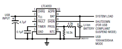
The schematic presented illustrates a minimal component solution for a USB battery charger utilizing the LTC4053 integrated circuit (IC) to create a fully compliant USB charger. This IC functions as a standalone linear charger designed for lithium-ion (Li-ion) batteries,...
This is a circuit of a step-down charge pump regulator for USB-powered devices. The critical design parameter of this circuit is the circuit area. The step-down charge pump regulator is designed to efficiently convert a higher input voltage from...
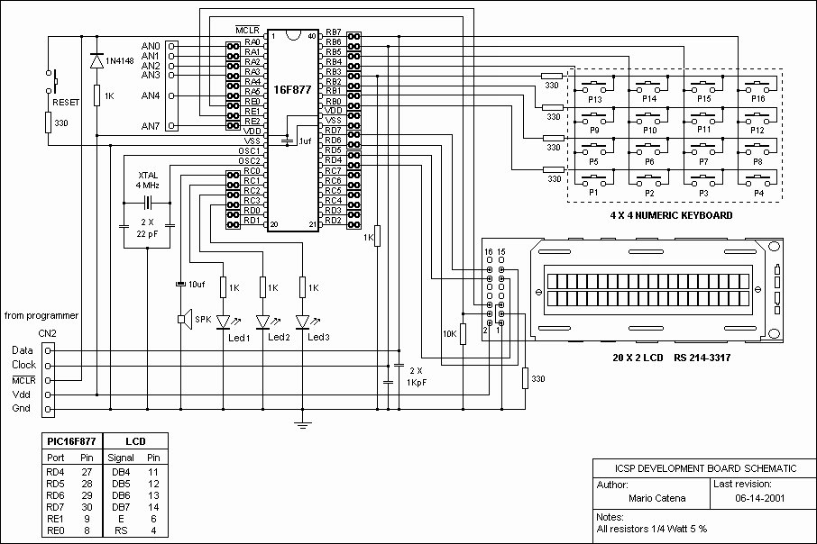
A schematic of a board featuring the PIC16F84 microcontroller, along with other compatible PIC microcontrollers that can be connected to the USB PICKit2 programmer. Additionally, there are concerns regarding the potential damage to the programmer when experimenting with oscillator...

A Microchip PIC18F4550 microcontroller has been acquired, but there is uncertainty regarding its potential applications. Further research is needed to explore various possibilities for programming and utilizing the microcontroller, as well as integrating additional electronic devices with it. The Microchip...
The Maker/hacker group Hive76, based in Philadelphia, PA, developed a compact serial terminal utilizing a TI Launchpad and an HD44780 LCD. The circuit diagram and code libraries are available for download, offering valuable resources that can be integrated into...