
4bit alphanumeric LCD interface 8051

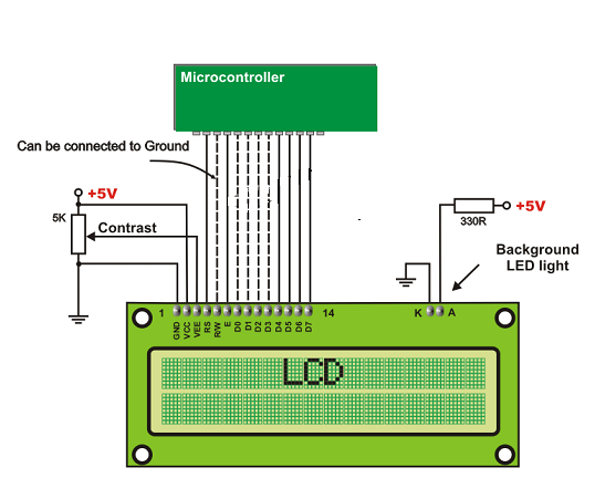
The described circuit leverages a microcontroller to interface with an LCD module, optimizing the use of GPIO pins while ensuring efficient data communication. The approach of utilizing seven GPIO pins allows for a streamlined connection, making the design suitable for applications with limited pin availability. The control lines—EN, RS, and RW—play crucial roles in managing the data flow between the microcontroller and the LCD.
In 4-bit mode, the data bus is reduced to four lines, which significantly conserves GPIO resources. The transmission sequence begins with setting the EN line low to prepare for data input. After configuring the RS line to indicate the type of data and ensuring the data bus is populated with the appropriate bits, the EN line is activated by setting it high. This transition signals the LCD to process the incoming data. The timing of this high signal is critical and must adhere to the specifications outlined in the LCD's datasheet to ensure reliable operation.
The RS line's dual functionality allows for flexible communication, distinguishing between command and data modes. The RW line provides a mechanism for reading status from the LCD, although it is predominantly used in write mode, thus simplifying the control logic in most applications.
In summary, this configuration is not only efficient in terms of pin usage but also supports a clear and organized method for controlling an LCD, making it ideal for various embedded systems and display applications. The systematic approach to data transmission and command execution enhances the reliability and performance of the circuit.using only total of 7 pins from your microcontrollers GPIO. So LCD module will cost only single port out of fours. >> The EN line is called "Enable. " This control line indicates to the LCD that we are sending it data. To send data to the LCD, the EN should be low (0) and then set the other two control lines and/or put data on the data bus. When the other lines are completely ready, bring EN high (1) and wait for the minimum amount of time required by the LCD datasheet (this varies from LCD to LCD), and end by bringing it low (0) again. >> The RS line is the "Register Select" line. When RS is low (0), the data is to be treated as a command or special instruction (such as clear screen, position cursor, etc.
). When RS is high (1), the data being sent is text data, which should be displayed on the screen. For example, to display the letter "T" on the screen we would set RS high. >>The RW line is the "Read/Write" control line. When RW is low (0), the information on the data bus is being written to the LCD. When RW is high (1), the program is effectively querying (or reading) the LCD. Only one instruction ("Get LCD status") is a read command. All others are written commands so RW will almost always be low. >>While using LCD in 4 bit data mode it saves 4 bits of our total GPIO lines, thatGƒ ƒ ‚Gƒ ‚ ’s why it is most commonly used. MSB of any data or commnad is sent first over 4 bits and then 4 LSB sent by shifting the data byte 4 times left.
🔗 External reference
Related Circuits
Learn how to interface a 16x2 LCD with the 8051 microcontroller. Download free source code for LCD interfacing with the 8051 microcontroller. The interfacing of a 16x2 Liquid Crystal Display (LCD) with the 8051 microcontroller is a common practice in...
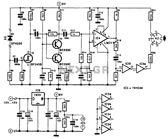
The receiver photodiode SFH250 is utilized to convert optical data pulses at a rate of 32.5 Kbps into electrical signals. The buffer T2 transmits these signals to a cascade amplifier consisting of transistors T3 and T4, followed by an...
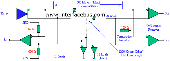
EIA/TIA-422 defines a balanced (differential) interface, specifying a single, unidirectional driver with multiple receivers (up to 32). RS-422 supports point-to-point and multi-drop circuits but not multi-point circuits (EIA-485). EIA-485 devices may be used in 422 circuits, but EIA-422 cannot...
This page describes how to build this full-bandwidth single-port (one input and one output) MIDI interface. The interface is buffered (that is, if the PC gets behind you won’t lose data) and it works in Windows 3.1 and Windows...
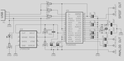
This is a high-quality preamplifier circuit with a built-in USB DAC designed for the Leachamp power amplifier. The schematic is derived from the PCM2902 datasheet. The circuit includes a DAC and ADC, SPDIF output and input, and an HID...
Temperature indicators and temperature-based products have garnered significant interest due to their numerous applications and various possible solutions, each presenting unique advantages and disadvantages. This concept focuses on a sensor interface that delivers high accuracy while minimizing board space....