
FPGA / CPLD 16x2 LCD Interface Circuit
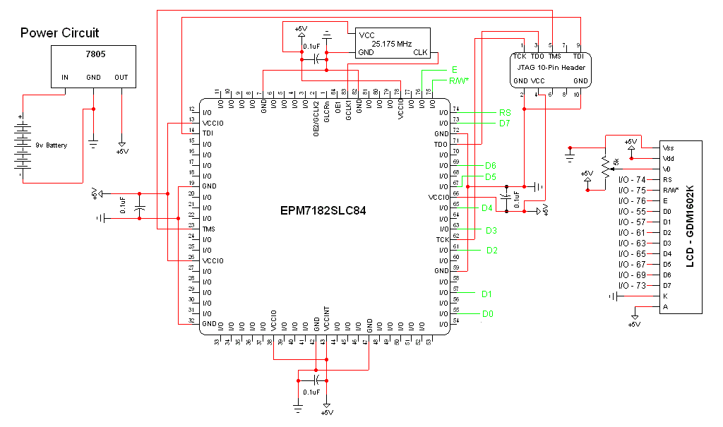
The schematic integrates several critical components to facilitate the operation of the CPLD-based system. The CPLD development board serves as the core processing unit, enabling complex logic operations and interfacing with peripheral devices. The 16x2 LCD (HD44780) is a widely used display module that provides a user interface for outputting information. In the 8-bit configuration, it connects to the CPLD via 11 digital I/O lines, which include data, control, and enable signals, ensuring efficient communication between the CPLD and the display.
The ByteBlasterMV is employed as a programming interface, allowing for the configuration of the CPLD through JTAG. This connection is vital for downloading the programmed logic into the CPLD, enabling it to execute the desired functions as defined in the design.
Power supply considerations are essential, with the LCD requiring a stable voltage and current for proper operation. The inclusion of a 5kΩ trimpot for contrast adjustment allows for fine-tuning the display visibility based on ambient lighting conditions.
The oscillator is a crucial component, providing the necessary clock signal for the CPLD to synchronize its operations. The choice of an oscillator with a frequency above 10 MHz ensures that the system operates efficiently, meeting timing requirements for the various logic functions implemented within the CPLD.
Overall, this schematic represents a well-thought-out integration of components that work together to create a functional CPLD-based project, allowing for both programming flexibility and user interaction through the LCD display.The schematic for this project is a modified version of the CPLD dev board schematic. There are a few new parts added for this project and you can see the completed schematic for this project below. The main parts in the schematic are the CPLD Dev Board, 16x2 LCD (HD44780) and ByteBlasterMV. The 16x2 LCD makes 11 digital I/O connections to the CPLD/FPGA when used in 8-bit mode (In 4-bit mode, only 7 connections are necessary). Since we`re using 8-bit mode all of these connections are necessary. The rest of the LCD`s pins are power connection and contrast from the 5k © trimpot. This protoboard for a cpld was developed by me a few years ago. It`s really just a PLCC CPLD in a socket with power and JTAG connectors for programming. This oscillator was chosen mostly at random. We needed some type of timing device to keep a reference to time and I had this one laying around. Generally if you can find a clock above 10 MHz you`ll be fine for this project. 🔗 External reference
Related Circuits
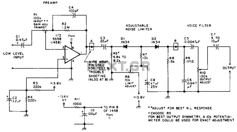
A preamplifier in the audio frequency range amplifies a noisy audio signal to drive a diode clipper. Suitable audio input levels would be in the 10-mV to 1-V range. The audio preamplifier circuit is designed to enhance weak audio signals, typically...
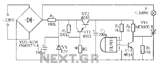
The H1.9811 single-channel flash control integrated circuit from Wuxi Love Core Microelectronics Co., Ltd. is designed for controlling flashing warning lights in road barricades. It features an integrated internal RC oscillator, frequency divider, output buffer amplifier, shaping circuit, and...
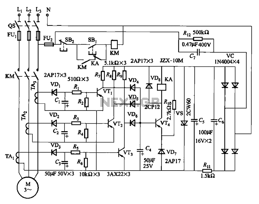
The current detection signal is obtained from three current transformers after rectification and filtering, resulting in three DC voltage outputs. These voltages are applied to transistors VT1, VT2, and VTa between the base and emitter. The signal is amplified...
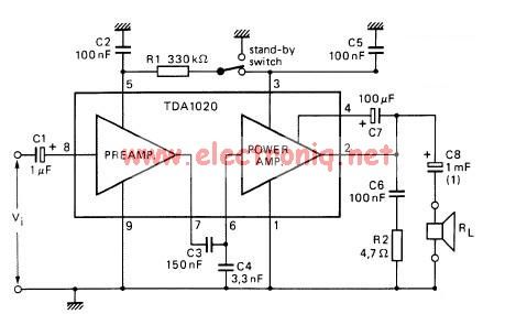
The TDA1020 is a monolithic integrated 12 W audio amplifier housed in a 9-lead single in-line (SIL) plastic package. Although it is designed primarily for car audio applications, it can also be utilized in various other audio applications. The TDA1020...
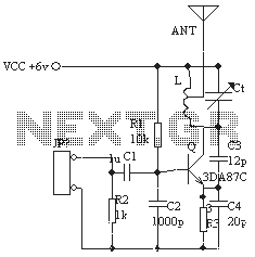
The ordinary triode 3DA87C is utilized to create a long-range FM transmitter circuit, which functions as a standard three-point oscillator circuit. This remote transmitter circuit is capable of large current emissions, achieving a range of up to 1 kilometer...
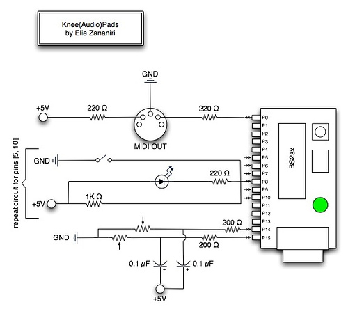
A few nice MIDI controller interfaces were discovered. The Knee(Audio)Pads are a wearable MIDI device. The MIDI controller interfaces mentioned provide innovative solutions for music production and performance. The Knee(Audio)Pads, in particular, represent a unique advancement in wearable MIDI technology....
Warning: include(partials/cookie-banner.php): Failed to open stream: Permission denied in /var/www/html/nextgr/view-circuit.php on line 713
Warning: include(): Failed opening 'partials/cookie-banner.php' for inclusion (include_path='.:/usr/share/php') in /var/www/html/nextgr/view-circuit.php on line 713