
PC-powered thermometer

Don`t apply too much solder, and be careful not to overheat parts (especially diodes and ICs). If necessary, let the part cool down before reworking. Most parts are polarised so be careful not to reverse them. Diode`s cathode (K) is marked by a black ring, and electrolytic capacitors negative pin is designated by a black strip. If you prefer to use tantalum capacitors, remember that their marking is reversed, with the black strip designating the positive leg!
I clean soldering iron tip before each solder joint, and use smallest diameter soldering alloy in order to apply as little solder as possible. I start applying a very small quantity of solder on the pad designed for pin 1 ONLY. I place the IC over the pads, and when all pads are perfectly aligned I clean the tip and put it on pin 1 until it gets soldered.
I verify that the IC is still correctly positioned (all pins centered and touching their respective pads). If it moved, I heat up pin 1 and restart, otherwise I continue soldering remaining pins, always cleaning soldering iron`s tip before each joint and applying very little solder.
Last step is soldering again pin 1 as its initial joint was made with very little solder. The LM2936Z5 voltage regulator needs special preparation for soldering. I had a through-hole part at hand, but I wanted it to solder on the SMT side of the board. The picture should make it clear how to bend and cut its pins for this purpose. The PCB is designed to fit between the pins of the serial port connector. This is the last part to solder. Don`t forget to bridge its pin 7 and 8 on the opposite side of the PCB. I usually clean residues of solder flux with a solvent like acetone, letting the circuit to dry completely before powering it. Once the board is tested and working, I apply a coat of spray clear varnish to protect the copper from oxidation.
Last step is to download and install the software. If you get confused by Microsoft Installer prompts (. in Italian) these screenshots ( first and second ) should make it clear. The circuit is derived from the Claudio Lanconelli`s PONYPROG programmer. The key component is Dallas Semiconductor`s DS1621 temperature sensor. It is a digital temperature sensor, meaning that it measures the temperature transforming it in a digital value (a binary number, that is a sequence of zeroes and ones as the bytes in your computer). Just apply 5V stabilized power, and the DS1621 is capable to transmit ambient temperature via an IIC (Inter-Integrated Circuit bus, also written I2C) serial bus.
This is a standard transmission scheme developed by Philips Semiconductors for connecting a moltitude of ICs together using just two wires: a clock wire (SCL) and a data wire (SDA). See the refe 🔗 External reference
Related Circuits
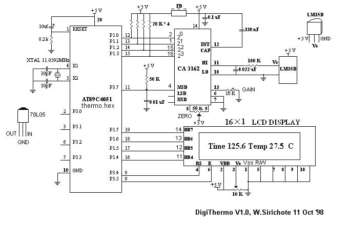
The MCU is an ATMEL 89C4051 CMOS Microcontroller featuring 4kB of code memory, 128 bytes of on-chip RAM, and 8-bit Port1 and Port3. The A/D chip is a HARRIS CA3162, which functions as a 3-digit digital voltmeter (DVM). This...
A digital thermometer is being planned for construction using an ATmega8 microcontroller and an LM335 temperature sensor. Guidance is sought on how to proceed with the project, particularly concerning the display components. The digital thermometer circuit utilizes the ATmega8 microcontroller,...
The circuit presented is designed to prevent burning one's tongue by monitoring the temperature of coffee. It consists of a voltage regulator, a temperature-to-voltage converter, a comparator, and two LEDs. In general, the circuit operates as follows: if the...
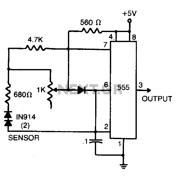
The sensor comprises two series-connected 1N914 diodes, which are part of the circuit of a 555 multivibrator. When wired as illustrated, the output pulse rate is proportional to the temperature of the diodes. This output is then fed into...
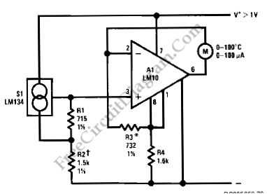
Using LM134 and LM10 integrated circuits, a thermometer can be constructed with a sensing range of -55 to 150 °C. The ideal meter for this circuit is a 0-200 µA. The proposed thermometer circuit utilizes the LM134, a current source...
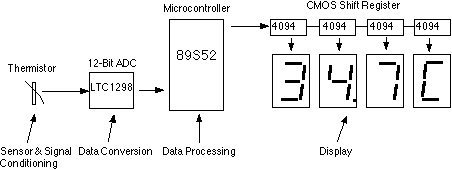
This assignment pertains to the course "Designing Microprocessor Based Instrumentation." The project features a board that utilizes a 12-bit ADC, a C program with digital filtering, and an LED display interface. It achieves a temperature reading sensitivity of 0.1°C....