
Thermistor Thermometer circuit
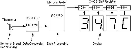
The described circuit is a microprocessor-based instrumentation system designed for temperature and humidity measurement. The heart of the system is the LTC1298 analog-to-digital converter, which provides high-resolution digital output from the analog signals received from the thermistor and an optional humidity sensor. The thermistor's output is conditioned using a voltage divider, ensuring that the voltage level fed into the ADC is within its operational range.
The microcontroller, ATMEL 89S52, orchestrates the entire operation, executing the C program that includes digital filtering algorithms to refine the raw ADC data. This filtering enhances measurement accuracy by minimizing noise and fluctuations in the readings. The microcontroller communicates with the ADC via a Serial Peripheral Interface (SPI), allowing for efficient data transfer and control.
The 4-digit 7-segment LED display provides a clear visual representation of the temperature readings, with a sensitivity of 0.1°C, making it suitable for applications requiring precise temperature monitoring. The display is driven by a 4094 CMOS shift register, which allows for efficient control of the LED segments through the microcontroller's output pins.
The design also incorporates an optional input channel for the ADC, facilitating the integration of additional sensors. In this case, the HIH-3160 Honeywell Relative Humidity Sensor can be connected to channel 1, enabling simultaneous measurement of temperature and humidity. This versatility enhances the system's applicability in various environmental monitoring scenarios.
Overall, the circuit design emphasizes simplicity and effectiveness, making it a suitable project for educational purposes in microprocessor-based instrumentation. The use of well-established components and interfaces ensures reliability and ease of implementation.This is my student assignment for the class "Designing Microprocessor Based Instrumentation". The board demonstrates the use of 12-bit ADC, writing c program with digital filtering and interface the LED display. The reading provides 0. 1C sensitivity. The optional input of the ADC is available for exercise with other input signals or sensors. The h ardware block diagram is shown in Fig. 2. The sensor is epoxy molded thermistor. The circuit for signal conditioning is simple voltage divider. The ADC is 12-bit SPI interface LTC1298 analog-to-digital converter. The microcontroller is ATMEL 89S52. The display has four digits 0. 5 inches 7-segment LED. The segment driver provides 32-bit CMOS output. The complete hardware schematic is shown in Fig 3. The ADC is 12-bit SPI interface LTC1298 or MC3202. There are two channels, CH0 and CH1. The input signal from thermistor for ADC channel 0 is simple voltage divider. Channel1 is available for other sensor. The sample shown in schematic is HIH-3160 Honeywell Relative Humidity Sensor. The ADC chip is interfaced with MCU, 89S52 with P1. 1, P1. 2 and P1. 3. The display has 4-digit LED. The 4094 CMOS shift register drives the LED directly. 🔗 External reference
Related Circuits
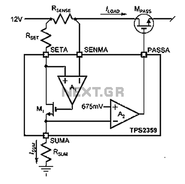
Amplifier A1 utilizes the voltage across the sense resistor sensors to monitor the load current ILOAD. The power management channel employs a similar circuit, with the distinction of integrating resistors RSENSE and RSET. Amplifier A1 is configured to measure the...
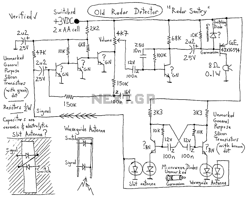
This integrated circuit (IC) requires fewer external components, making it simpler for beginners to assemble it on a veroboard. The original circuit was sourced from its datasheet. A slightly modified version of the circuit is presented below. This circuit...
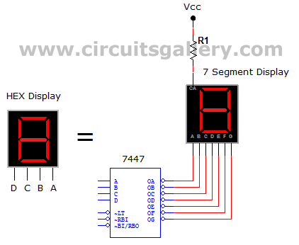
This circuit defines seven levels in a reservoir. The sensed values are connected to an encoder circuit, which consists of a 74148 integrated circuit (IC), functioning as an 8-line to 3-line encoder. The next section features a HEX display,...

This is a simple VE7GC Popcorn RF preamplifier designed by Dick Pattinson. The circuit features a single tuned circuit at the input stage, allowing direct connection to a mixer or product detector in a straightforward receiver project. Adjustable RF...
The voice recorder's entry information can be stored for 100 years, repeated 100,000 times, with low power consumption. It requires a 5-6V DC power supply and has a recording current of 2 mA. The voice recorder circuit is designed to...

A simple single-chip FM transmitter circuit with a diagram and schematic using the IC MAX 2606, which is a high-performance voltage-controlled oscillator (VCO). The FM transmitter circuit utilizing the MAX 2606 is designed for efficient frequency modulation of audio signals....