
PC terminal using a TV
Button by button assembling of keyboard is complicated and mechanical design is a weak point in hobby construction. Special keyboards are usually inaccessible or expensive. That's why I have chosen standard IBM PC keyboard. PC keyboard solves as design as character variability - there are all characters on keyboard. Economic view is very advantageous and accessibility is almost unbeatable. The size is disadvantage of PC keyboard but beside TV set it doesn't matter.
I have developed 2 versions of TV terminal. Built-in version is designed for utilization in device. The second version is standalone device with external power source.
The described TV terminal accomplishes these results:
Display mode: black and white
Text mode: 40 characters x 25 lines
Semigraphic mode: 80 x 75 "points"
Printable characters: ASCII 32 - 127
Keyboard: IBM PC AT compatible
Control characters: 11
Serial line speeds: 1200 Bd to 115.2 kBd
Power supply: 9 - 12 V or 5 V (built-in version)
Current consumption: cca 30 mA + keyboard consumption
As you can see wiring diagram is very easy. Most of the functions are centred in the microcontroller U1. There must be minimally 1 kB RWM for 40x25 character screen. I have selected well-known and available type - ATmega8.
The U1 microcontroller has to maintain 3 independent processes:
- Video signal generation.
- Character reception from the keyboard, decoding and dispatch to serial line.
- Receiving characters from serial line and storing it in the memory.
Independency for every of these 3 processes was the most complicated task. Video signal must be generated utterly on the dot. Program was created in assembler and compiled code is here.
Microcontroller clock is on maximum frequency - 20 MHz. Frequency 22 MHz would be better, but for reproducibility I accepted 20 MHz. This backtracking brings slight differences in the horizontal width of pixels. Forgive me - it is only hobby design (or maybe you will notice this never :-). IBM PC AT compatible keyboard can be connected to terminal. You can use both keyboard types - with PS2 connector or original DIN5. Standalone version is ready for PS2 connector. Use DIN5/PS2 reduction for keyboard with old DIN5 connector.
You can type printable characters directly. Special characters (e.g. control characters or characters above 127) can be placed as well. Left ALT must be pressed at first and then 2 hexadecimal characters follow. E.g.: for LF character press successively keys "left ALT" + "0" + "A". This way you can place all characters 0 to 255.
Special keyboard mode is remnant from the development time. When you press F12 key then keyboard is switched into "SCAN mode". Pressing of key will produce text string with base SCAN code of the key. E.g. press keys "A" and "B" - terminal will send text string "1C 32 ". Key F12 stops this mode as well. The power supply voltage regulator and logic level converter are included in the standalone version. To keep circuit easy I selected (inspired by biprog) simple converter with 2 transistors. There is no problem with short serial line. But if you connect long wires with bigger capacity then communication can produce errors in higher speeds. Be careful with used keyboard. Consumption most of them is reasonable low, but there are types with consumption above 100 mA. High current causes overheating of U2 voltage regulator. Use voltage regulator 7805 in the TO220 case or reduce power supply voltage in this event.
The described electronic circuit utilizes a microcontroller (U1) to implement a TV terminal that can display data received via a serial connection. The circuit is designed to operate with an IBM PC AT compatible keyboard and can display text in a black-and-white format, supporting 40 characters across 25 lines, or a semigraphic mode of 80 by 75 points. The microcontroller, chosen for its availability and performance, is the ATmega8, which requires a minimum of 1 kB of RAM to handle the 40x25 character display.
The microcontroller is responsible for generating a video signal, receiving characters from the keyboard, decoding them, and transmitting them over a serial line. It also stores incoming characters from the serial line into memory. The design emphasizes the need for the microcontroller to manage these processes independently to ensure smooth operation. The clock frequency is set to 20 MHz to balance performance and reproducibility, although a higher frequency could improve pixel rendering.
The circuit includes a power supply that can operate within a range of 9-12 V or 5 V for the built-in version, with a current consumption of approximately 30 mA, excluding keyboard power. A simple voltage regulator and logic level converter are integrated into the standalone version to facilitate proper operation with various keyboard types, including both PS2 and DIN5 connectors.
In addition to standard character input, the terminal supports special character entry using a combination of the left ALT key and hexadecimal codes. A SCAN mode is also implemented for debugging purposes, allowing the user to see the SCAN code for each key pressed. The design is robust yet simple, allowing for ease of assembly and operation, making it suitable for hobbyists and educational purposes.When you use microcontrollers in your designs, sometime you face a problem how to show user required data. Several LEDs, 7 segment display or LCD module can be solution. But if you must show a lot of information simultaneously, it can be difficulty. Large LCD modules are expensive and graphic modules require complicated control. You can solve it with a help of PC. Just send data via serial line to the computer and display everything on computer's display. I have had to solve the same problem some time ago. I have chosen normal small TV set for that. A lot of families change TV in this time because of digital broadcasting or modern flat and slim LCD and plasma displays.
So they put older TV set away and it is dormant somewhere. Or you can buy older TV very cheap. The display unit must be maximum easy. For data displaying is text mode with semigraphic mode sufficient. Just only 1 integrated circuit - microcontroller - must guarantee every function of the unit. A keyboard will be useful for data input. "Button by button" assembling of keyboard is complicated and mechanical design is a weak point in hobby construction. Special keyboards are usually inaccessible or expensive. That's why I have chosen standard IBM PC keyboard. PC keyboard solves as design as character variability - there are all characters on keyboard. Economic view is very advantageous and accessibility is almost unbeatable. The size is disadvantage of PC keyboard but beside TV set it doesn't matter. I have developed 2 versions of TV terminal. "Built-in" version is designed for utilization in device. The second version is standalone device with external power source. The described TV terminal accomplishes these results: Display mode: black and white Text mode: 40 characters x 25 lines Semigraphic mode: 80 x 75 "points" Printable characters: ASCII 32 - 127 Keyboard: IBM PC AT compatible Control characters: 11 Serial line speeds: 1200 Bd to 115.2 kBd Power supply: 9 - 12 V or 5 V (built-in version) Current consumption: cca 30 mA + keyboard consumption As you can see wiring diagram is very easy.
Most of the functions are centred in the microcontroller U1. There must be minimally 1 kB RWM for 40x25 character screen. I have selected well-known and available type - ATmega8. The U1 microcontroller has to maintain 3 independent processes: - Video signal generation. - Character reception from the keyboard, decoding and dispatch to serial line. - Receiving characters from serial line and storing it in the memory. Independency for every of these 3 processes was the most complicated task. Video signal must be generated utterly on the dot. Program was created in assembler and compiled code is here. Microcontroller clock is on maximum frequency - 20 MHz. Frequency 22 MHz would be better, but for reproducibility I accepted 20 MHz. This backtracking brings slight differences in the horizontal width of pixels. Forgive me - it is only hobby design (or maybe you will notice this never :-). IBM PC AT compatible keyboard can be connected to terminal. You can use both keyboard types - with PS2 connector or original DIN5. Standalone version is ready for PS2 connector. Use DIN5/PS2 reduction for keyboard with old DIN5 connector. You can type printable characters directly. Special characters (e.g. control characters or characters above 127) can be placed as well. Left ALT must be pressed at first and then 2 hexadecimal characters follow. E.g.: for LF character press successively keys "left ALT" + "0" + "A". This way you can place all characters 0 to 255. Special keyboard mode is remnant from the development time. When you press F12 key then keyboard is switched into "SCAN mode". Pressing of key will produce text string with base SCAN code of the key. E.g. press keys "A" and "B" - terminal will send text string "1C 32 ". Key F12 stops this mode as well. The power supply voltage regulator and logic level converter are included in the standalone version. To keep circuit easy I selected (inspired by biprog) simple converter with 2 transistors. There is no problem with short serial line. But if you connect long wires with bigger capacity then communication can produce errors in higher speeds. Be careful with used keyboard. Consumption most of them is reasonable low, but there are types with consumption above 100 mA. High current causes overheating of U2 voltage regulator. Use voltage regulator 7805 in the TO220 case or reduce power supply voltage in this event. 🔗 External reference
Related Circuits
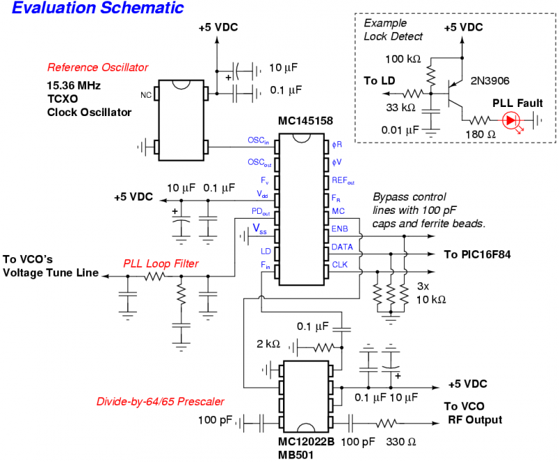
The Motorola MC145158 is a dual-modulus, serial-input PLL frequency synthesizer commonly utilized in older Motorola cellular phones. For detailed technical specifications, refer to the MC145158 datasheet. Although the MC145158 is no longer in production, it can occasionally be found...

A simple touch dimmer circuit diagram using the TT6061 IC, which is a touch control integrated circuit used for light dimmer circuits and lamp dimmer circuits. The touch dimmer circuit utilizing the TT6061 IC is designed to provide a user-friendly...
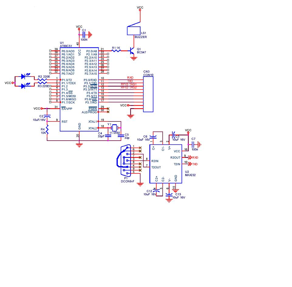
A project is being developed utilizing RFID (Radio Frequency Identification) technology. The microcontroller chosen for this project is the AT89C51/52/S52. Serial communication is being implemented using RS-232. The project involves the integration of RFID technology for identification and data exchange...
This article describes a 2-Input alarm developed on the PIC LICK-1 Module using a Microchip PIC16F628-04. The program uses the internal 4MHz oscillator and if any other frequency is used, the timer values will need to be changed. A...
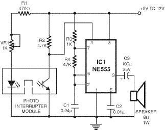
This smoke detector utilizes a 555 timer circuit along with common electronic components. The photo interrupter module serves as the smoke detection element, while the 555 timer is configured in astable mode to function as an audio frequency oscillator,...
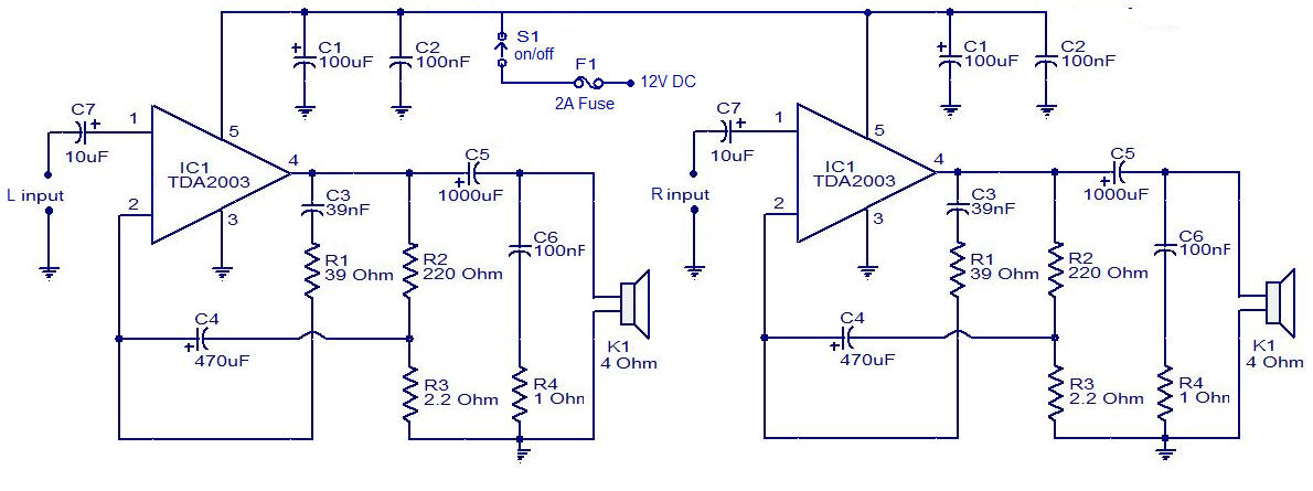
The circuit is easy to construct. The TDA2003 is an integrated radio amplifier from ST Microelectronics that features short circuit protection for all pins, thermal protection, low harmonic distortion, and low crossover distortion. In the circuit provided, the TDA2003...