
Using the MC145158 PLL Frequency Synthesizer

The MC145158 is intended to be programmed via a microcontroller using a standard serial-input data stream. It features pins for the shift clock (CLK, pin 9), serial data input (DATA, pin 10), and latch enable (ENB, pin 11). These three lines dictate the programming process of the PLL. Once programmed, the counter values remain intact until power is removed from the circuit. The counters must be programmed with the Most Significant Bit (MSB) first. A logic high on the control bit pin latches the data from the shift register into either the reference divider or the /N, /A latches, depending on the control bit state. When the control bit is set to logic low, it allows for data modification in the shift registers without affecting the counters. The ENB pin is typically held low and pulsed high to transfer data to the latches.
To program the counter data into the MC145158, the voltage on the DATA pin must be set to +5 volts for a logic 1 and 0 volts (ground) for a logic 0. Subsequently, the CLK pin should be raised to +5 volts from its initial state of 0, then quickly returned to 0 volts. This process should be repeated 15 times to load the R-Counter value (14 bits plus one control bit). After completing this, the ENB pin should be raised to +5 volts from its initial state of 0 and then quickly returned to 0 volts to permanently latch the data into the counters. The same procedure applies to load the /N and /A counters, requiring a total of 18 bits (17 bits plus one control bit) for programming.
The MC145158 is a crucial component in frequency synthesis applications, particularly in older communications technology. Its ability to be programmed via serial input allows for flexibility in designs that require precise frequency generation. The careful management of the control signals and timing is essential for the successful operation of the device, ensuring that the desired frequencies can be achieved reliably. The presence of alternative components, such as the MB87001A, provides options for designers working with legacy systems, enabling continued functionality despite the discontinuation of the MC145158.The Motorola MC145158 is a dual-modulus, serial-input PLL frequency synthesizer which is commonly used in older Motorola cellular phones. Refer to the MC145158's datasheet for the nitty-gritty technical details. The MC145158 is no longer manufactured, but it does pop up from time-to-time in surplus electronic stores.
Digi-Key used to carry it, part number MC145158DW2-ND. The Fujitsu equivalent is the MB87001A, which is very common in old Japanese-manufactured (Uniden, Toshiba, etc.) cellular phones. The programming of the MB87001A is the same as the MC145158, but the technical specs to the MB87001A are slightly different.
The maximum input frequency for the MC145158 is only around 20 MHz when run at +9 VDC. It drops to around 15 MHz at +5 VDC. The R-Counter reference frequency divider range is between 3 and 16,383. The N-Counter can be between 3 and 1,023. The A-Counter dual-modulus range is between 0 and 127. When using an external dual-modulus prescaler set to /64 (divide-by-64), such as a Motorola MC12022 or Fujitsu MB501, don't exceed a value of 63 for the A-Counter. The MC145158 is designed to be programmed via a microcontroller using a standard serial-input data stream. The MC145158 has pins for the shift clock (CLK, pin 9), serial data input (DATA, pin 10), and latch enable (ENB, pin 11).
These three lines control how and when the PLL is programmed. Once programmed, all the counter's values will remain programmed until power is removed from the circuit. Also, the counters must be programmed Most Significant Bit (MSB) first. A logic high on this pin latches the data from the shift register into the reference divider or /N, /A latches depending on the control bit.
The reference divider latches are activated if the control bit is at a logic high and the /N, /A latches are activated if the control bit is at a logic low. A logic low on this pin allows the user to change the data in the shift registers without affecting the counters.
ENB is normally low and is pulsed high to transfer data to the latches. What this means, in English, is that to program the counter data into the MC145158, you need to set the voltage on the DATA pin to +5 volts for a logic 1, and 0 volts (ground) for a logic 0. You'd then raise the CLK pin to +5 volts, from it's initial value of 0, then quickly bring it back to 0 volts.
Do this 15 times to load the R-Counter value (14 bits, plus one control bit). When finished, raise the ENB pin to +5 volts, from it's initial value of 0, then quickly bring it back to 0 volts. The data is permanently latched into the counters. To load the /N and /A counters, do the same again, but you'll need to load 18 bits (17 bits, plus one control bit).
🔗 External reference
Related Circuits
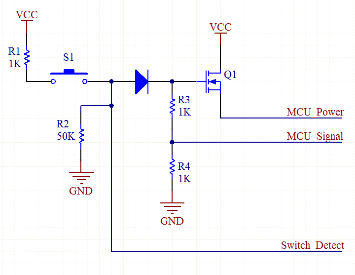
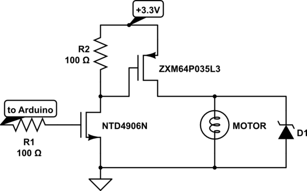
An explanation of how the circuit operates. The TPS_EN line is initially low, as it is connected to a 10k pull-down resistor (not shown in the schematic). When the user presses switch S2, the MOSFET Q2 is activated because...
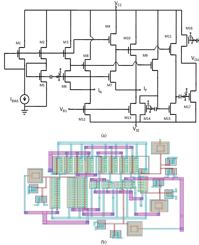
A comprehensive design procedure is proposed for the development of Field-programmable/Reconfigurable Analog Integrated CMOS circuits. Instead of relying on iterative simulation steps to meet design specifications by adjusting the W/L ratios of the FETs, first-order classroom equations are utilized...
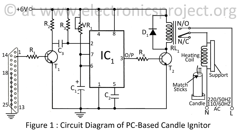
A PC-based candle ignitor is a verified project designed for computer students, utilizing a 555 timer circuit to ignite a candle. The project includes a computer circuit diagram and software code written in C. The PC-based candle ignitor project integrates...
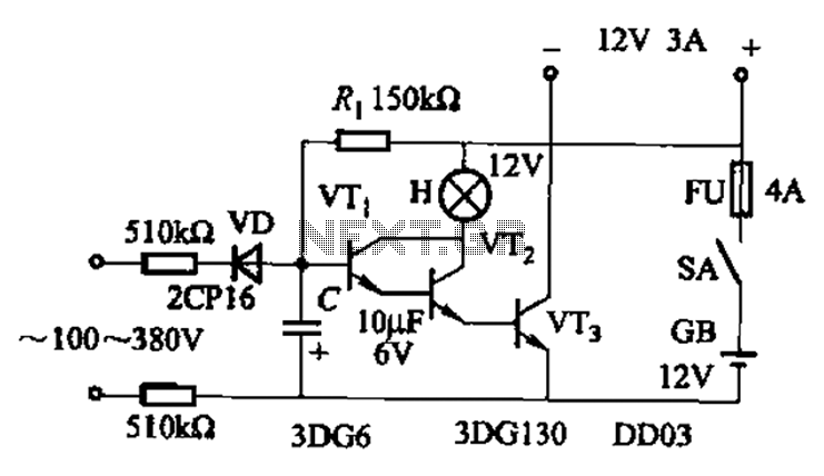
An AC-DC power supply without a power switching circuit is typically utilized for lighting load circuits. Once the power grid is restored, the standby power supply automatically switches on. An automatic switching circuit using a transistor is implemented, with...
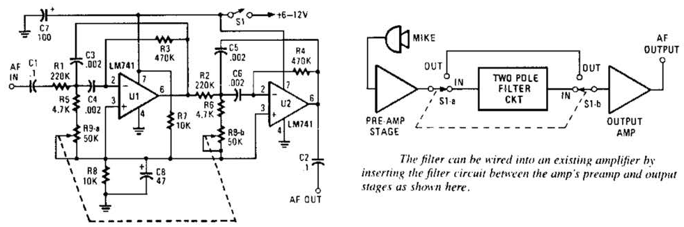
This variable-frequency audio bandpass filter is constructed using two 741 operational amplifiers connected in cascade. The two 741 op amps are configured as identical RC active filters and are cascaded to enhance selectivity. The filter's tuning range spans from...
Charge a simple servo that only has + and - pins. Typically, the - pin is connected to ground, while the + pin is connected to a digital output from an Arduino. This setup works, but the servo operates...