
PCB designing using KiCAD Tutorial

The astable multivibrator circuit using the 555 timer IC is a fundamental electronic configuration that generates a continuous square wave output without requiring any external triggering. The 555 timer, a versatile integrated circuit, can be configured in various modes, and the astable mode is particularly useful for applications such as clock pulses, LED flashers, and tone generation.
In the astable configuration, the 555 timer operates between two states: high and low, continuously switching between them at a frequency determined by external resistors and capacitors. The circuit typically includes two resistors, R1 and R2, and a capacitor, C1, connected to the 555 timer in the following manner:
1. **Connections**:
- Pin 1 (GND) is connected to the ground.
- Pin 8 (VCC) is connected to the positive supply voltage, typically between 4.5V to 15V.
- Pin 2 (Trigger) and Pin 6 (Threshold) are connected together and also connected to the junction of R2 and C1.
- Pin 3 (Output) provides the square wave output.
- Pin 4 (Reset) is connected to VCC to disable the reset functionality.
- Pin 5 (Control Voltage) is often connected to ground through a capacitor (typically 0.01 µF) to filter noise.
- Pin 7 (Discharge) is connected to the junction of R1 and R2.
2. **Operation**:
- When power is applied, C1 begins charging through R1 and R2. The voltage across C1 increases until it reaches 2/3 of VCC, at which point the 555 timer switches its output to low, causing C1 to discharge through R2 and pin 7 until it drops below 1/3 of VCC. This cycle repeats, generating a continuous square wave.
3. **Frequency Calculation**:
- The frequency (f) of the output square wave can be calculated using the formula:
\[
f = \frac{1.44}{(R1 + 2R2) \times C1}
\]
- The duty cycle, which determines the ratio of the high state to the total period, can also be calculated, typically resulting in a duty cycle less than 50% due to the configuration of the resistors.
This simple astable multivibrator circuit demonstrates the basic principles of timing and oscillation in electronics, providing a practical application for the 555 timer IC in various projects.Here is a quick guide, which will help you to get started off with kiCAD. In this tutorial we will be considering a simple astable multivibrator circuit using 555 timer IC 🔗 External reference
Related Circuits
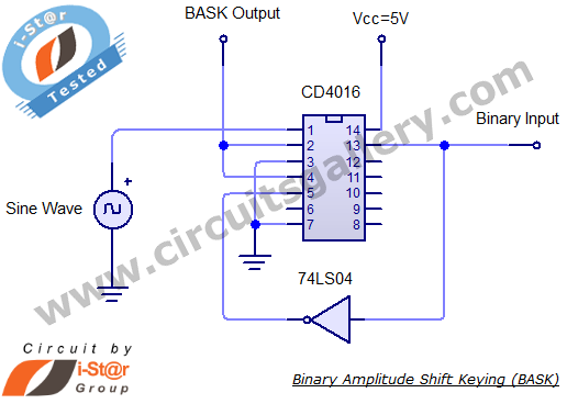
Binary Amplitude Shift Keying (BASK), also known as On-Off Keying (OOK), is a digital modulation technique where the amplitude of the carrier signal is altered according to binary data. This modulation scheme is utilized for transmitting digital information over...
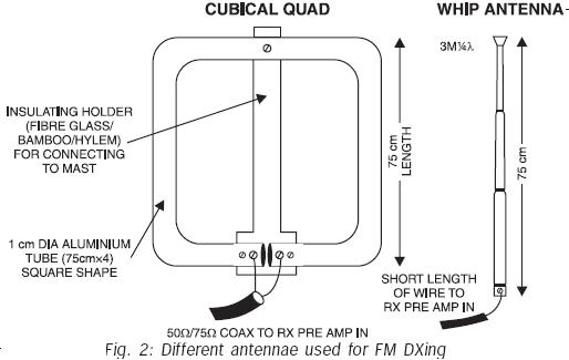
FM transmissions can be received within a range of 40 km. In fringe areas, the signal may be very weak. FM DXing refers to the practice of receiving distant stations (1500 km or more) on the FM band (88-108...
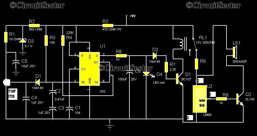
Numerous circuits are available for infrared burglar alarms; however, the transmitter section of these circuits can be complex and may require assembly. This burglar alarm circuit utilizes a standard DVD remote as the transmitter, which reduces both cost and...
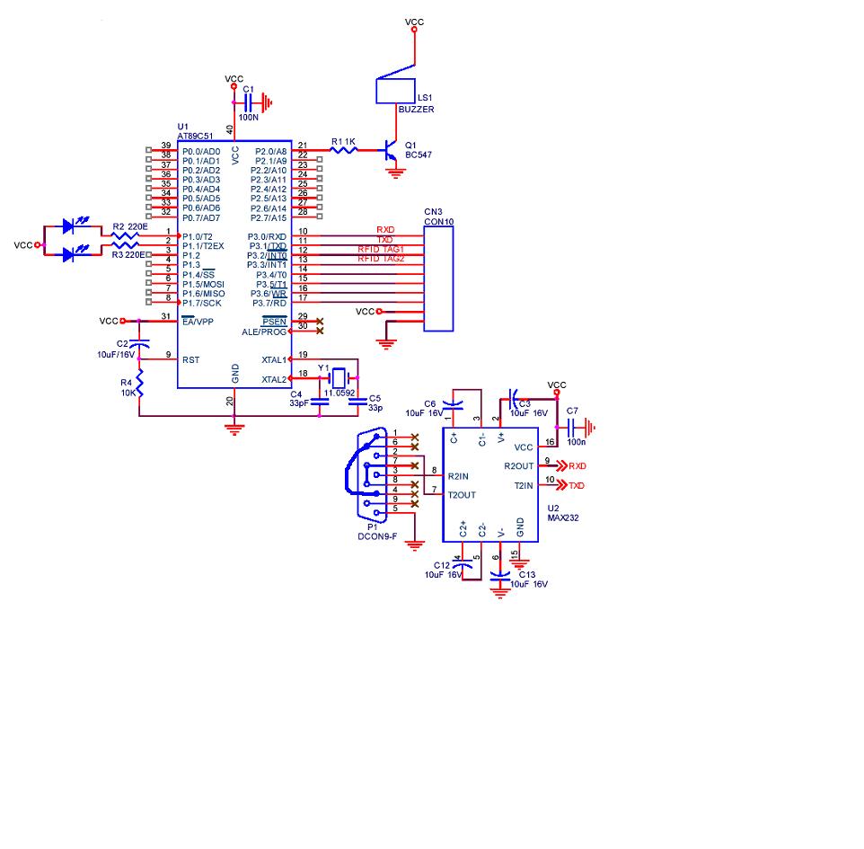
A project is being developed utilizing RFID (Radio Frequency Identification) technology. The microcontroller chosen for this project is the AT89C51/52/S52. Serial communication is being implemented using RS-232. The project involves the integration of RFID technology for identification and data exchange...

The solar orientation circuit employs a comparator with window control to maintain engine idle as long as the two LDRs (light-dependent resistors) are exposed to equal illumination. In this scenario, half the supply voltage is applied to the non-inverting...
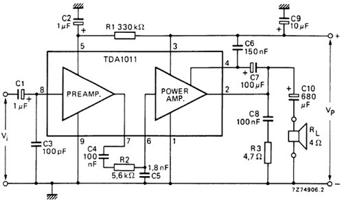
The following schematic illustrates the design of a 4 Watt Amplifier Circuit Diagram intended for portable radio applications, utilizing the TDA1011 integrated circuit from Philips Semiconductor. The 4 Watt Amplifier Circuit is designed to provide audio amplification in portable radio...