
Game Circuits
The game show timer circuit is structured to facilitate an interactive experience among multiple contestants. It employs a straightforward design that allows for easy assembly and modification. The circuit's core consists of a power supply, control devices, and output indicators (lamps). The use of SCRs or triacs as control devices is crucial, as they enable the switching of high current loads (the lamps) while being triggered by low current signals from the pushbuttons.
The inclusion of a 470-ohm resistor from the gate to the negative terminal is a critical design element that enhances reliability by reducing the likelihood of false triggering, which could occur due to noise or interference. The choice of a 9-volt zener diode ensures that the control voltage remains stable, allowing for consistent operation of the SCRs or triacs.
The circuit's modularity is one of its standout features. Each contestant station can be independently constructed and then connected back to a central base unit, allowing for scalability without a significant increase in complexity. This modular approach is particularly beneficial in environments where multiple contestants may participate simultaneously, such as in a game show setting.
The use of a piezo buzzer in conjunction with a relay adds an auditory feedback mechanism, further engaging contestants and providing immediate feedback on their actions. The design allows for flexibility in component selection, accommodating various types of components that may be available, which is advantageous for hobbyists and educators alike.
In summary, this game show timer circuit is an excellent project for beginners, combining fundamental electronic principles with practical application in a fun and interactive format. Its design promotes learning and experimentation, making it a valuable educational tool.Here is a really simple game show timer designed with the beginner in mind! The power source is an ordinary 12 volt lantern battery or battery pack made up of C or D cells. The lamps may be ordinary flashlight bulbs; the prototype uses 750 mA Krypton types (KPR112) with wires soldered directly onto the bulbs. The control devices may be just about any non-sensitive gate SCRs or triacs with a current rating of a few amps. Avoid SCRs that trigger with 100s of microamperes; you want a gate trigger current of a few mA or else you will have trouble with more than one light coming on at once. A low value resistor, perhaps 470 ohms may be added from gate to -12 volts to reduce false triggering.
SCRs are shown and triacs may be substituted by connecting MT1 to the negative battery terminal and MT2 to the lamps. In fact, the two types of devices could probably be mixed if that is what the junk box has to offer! (But not sensitive gate types!) The zener is an ordinary 9 volt, 1 watt type like the 1N4739. The 100 ohm resistor may be any type with a rating of 1/8 watt or more. The reset/power button is an ordinary toggle switch and the pushbuttons are any convenient normally-open type.
The entire circuit may be built into one box with two wires running out to each contestant`s pushbutton switch or the SCR, lamp, and switch may be in a remote box for each contestant with three wires running back to the base unit. Many more than three contestants may be added by repeating the pattern. Here is what you see: The three lower lamps are soldered directly to the MT2 terminals of triacs (anodes if SCRs are used).
These particular triacs (RCA T2710) come with an integral heat sink connected to MT2. The gate leads (on the left) connect to the pushbuttons (red wires) and the other end of the pushbuttons all go to the resistor-zener junction (white wires). The 100 ohm resistor is the tiny brown part and the zener is the silver part. The brown wires connect the MT1 terminals (cathodes) to the negative battery wire. The red positive battery wire connects to the base unit lamp which is directly connected to the other three bulbs.
(Bulb "polarity" is not important. ) The schematic shows the 2200uF capacitor in series with a 5 or 6 volt reed relay`s coil; the larger the capacitor, the longer the buzz. A 9 volt battery is connected in series with the relay`s normally-open contacts and a piezo buzzer. The separate battery is highly recommended to prevent electrical noise from the buzzer from triggering the other SCRs.
Other battery and buzzer voltages/types will also work. Here is a somewhat more complex version that uses easily found bipolar transistors. Note that it requires only two wires between stations and base and those wires can be connected anywhere on the "buss". (You can wire each station back to the base unit or "daisy chain" the stations from one to the next with only one set of wires going back to the base unit.
) The game show timer determines which contestant presses their button first by lighting a lamp and ringing a bell and the slower contestants are locked out. The circuit is convenient in that only two wires are needed to interconnect the stations and the wires may all go back to the base unit or they may be "daisy-chained" between stations.
There is no electronic limit on the number of stations. The circuit uses a 24 volt power source and 12 volt lamps when built as shown but the experienced experimenter may scale these voltages along with the zener voltages if desired. 🔗 External reference
Related Circuits
The circuit presented is a standard Colpitts oscillator, commonly utilized in many amateur radio homebrew transmitters. This specific circuit is designed to operate effectively within a frequency range of 1500 kHz to 8000 kHz. To accommodate lower frequencies, it...
This discussion covers three different Xenon flashing circuits from disposable cameras. From these circuits, unique techniques not found in any theoretical literature will be presented. The first circuit consists of six building blocks. An old disposable flash camera and...
An integrated circuit is precisely that: an integrated circuit. These small packages combine numerous individual components to perform a specific function. They vary in shape and size depending on their complexity. They are categorized into functions such as audio,...
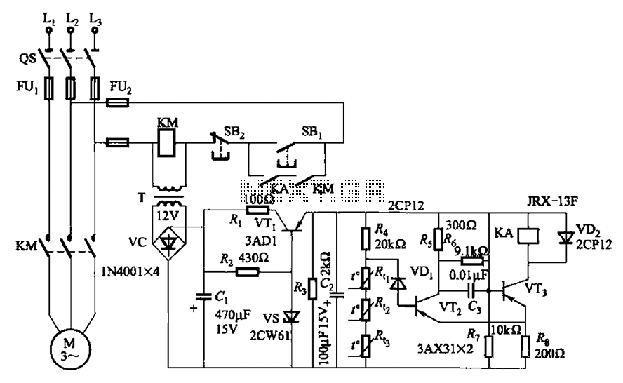
A P-type transistor (VT2, VT3) and other components form a common emitter-coupled trigger, functioning as a Schmitt trigger device. This setup serves as a switching circuit to detect changes in the resistance of a PTC thermistor, thereby controlling the...

This is a design for a scoring game circuit suitable for any occasion where dice are used. The circuit utilizes a NE555 timer, a 74LS192 counter, a 74LS247 decoder, and a seven-segment LED display. The timer IC1 generates a...
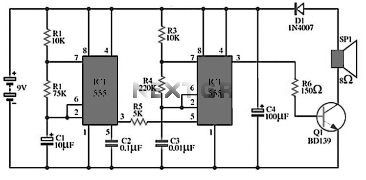
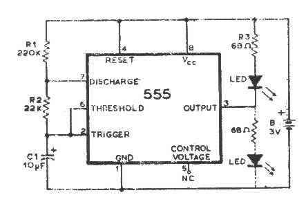
The circuit utilizes IC1 to create an astable multivibrator configuration. It is designed to generate a low-frequency output of approximately 1 Hz at pin 3, which is determined by the resistor values R1, R2 and capacitor C1. The output...
Warning: include(partials/cookie-banner.php): Failed to open stream: Permission denied in /var/www/html/nextgr/view-circuit.php on line 713
Warning: include(): Failed opening 'partials/cookie-banner.php' for inclusion (include_path='.:/usr/share/php') in /var/www/html/nextgr/view-circuit.php on line 713